@beegee , further I will keep communication in forum only. yes I am using USB connector to send AT commands. Is there any sequence of AT commands to be send to device to detect SIM card?
Thank you
Hai, I will try to convey information properly, at starting I was checking the output from the Termite app, there I observed for at+version command response was Firmware Version: RUIv3.0.015 OK
and for response of different AT commands also I was able to observe then I wanted to implement MQTT functionality so I flashed code written in Arduino IDE through Jlink then through USB also Iam able flash written code. Now if I open Termite app I could see the output of written code. If I send at+version also it shows AT command not found.
Can you share your code?
#ifndef rak5010
#error “Please select WisTrio Cellular RAK5010 Board and compile again”
#endif
String command; //String to store BG96 commnads
//Read data from BG96
void bg96_read() {
while(Serial1.available()>0) {
Serial.print((char)Serial1.read());
delay(1);
}
}
//Write commnads to BG96
void bg96_write(const char *command) {
while(*command){
Serial1.write(*command);
command++;
}
delay(1000);
}
void setup()
{
Serial.begin(115200);
Serial1.begin(115200, RAK_CUSTOM_MODE); // Serial1 on RAK5010 is connecting to BG96 internally
delay(1000);
// NOTE:While turning Off "Auto Display Cellular Response" on ArduinoIDE menu, make sure open the code below
//      Otherwise you will miss the response from BG96.
// Setup a timer to get data from BG96
if (api.system.timer.create(RAK_TIMER_0, (RAK_TIMER_HANDLER)bg96_read, RAK_TIMER_PERIODIC) != true) {
    Serial.println("Creating timer failed");
} else if (api.system.timer.start(RAK_TIMER_0, 1000, NULL) != true) { // Set the period you like ,Default 1 second
    Serial.println("Starting timer failed");
}


// Send "AT" to check BG96 is working
command = "AT\r";
bg96_write(command.c_str());

command = "ATI\r";
bg96_write(command.c_str());
delay(1000);

command = "AT+GSN\r";
bg96_write(command.c_str());
delay(1000);

command = "AT+CFUN=0\r";
bg96_write(command.c_str());
// delay(1000);

command = "AT+CPIN?\r";
bg96_write(command.c_str());
delay(1000);

command = "AT+CFUN=1,1\r";
bg96_write(command.c_str());
delay(10000);

command = "AT+CPIN?\r";
bg96_write(command.c_str());
delay(1000);

 command = "AT+QSIMDET=1,0\r";
bg96_write(command.c_str());
delay(1000);

command = "AT+CPIN?\r";
bg96_write(command.c_str());
delay(1000);
}
void loop()
{
command = “AT+CIMI\r”;
bg96_write(command.c_str());
delay(1000);
command = "AT+CSQ\r";
	bg96_write(command.c_str());
	delay(1000);
}
OUTPUT OF ABOVE CODE
OK
AT+CFUN=0
OK
AT+CPIN?
+CME ERROR: 13
AT+CFUN=1,1
OK
RDY
APP RDY
AT+CPIN?
+CME ERROR: 10
AT+QSIMDET=1,0
OK
AT+CPIN?
+CME ERROR: 10
AT+CIMI
+CME ERROR: 3
AT+CSQ
+CSQ: 99,99
OK
AT+CIMI
+CME ERROR: 3
What are the Blue and Red LED on the RAK5010 showing?
After power up, the Blue should be on and the Red should be blinking. This will change after the BG96 connected to the cellular network.
If they are both off, then press the button with the label PWR.
Make sure you have a battery attached.
Can you try to run attached code? It is handling the response from the BG96 differently.
RAK5010_MQTT.ino (4.7 KB)
Output on my RAK5010 (SIM card detected, but no connection)
2023-07-19 09:24:16 --> Version: RAK5010
2023-07-19 09:24:27 --> Modem response after start:
2023-07-19 09:24:27 --> ATI
2023-07-19 09:24:27 -->
2023-07-19 09:24:27 --> Quectel
2023-07-19 09:24:27 --> BG96
2023-07-19 09:24:27 --> Revision: BG96MAR02A07M1G
2023-07-19 09:24:27 -->
2023-07-19 09:24:27 --> OK
2023-07-19 09:24:27 -->
2023-07-19 09:24:27 --> BG96 power up!
2023-07-19 09:24:28 --> AT
2023-07-19 09:24:28 -->
2023-07-19 09:24:28 --> OK
2023-07-19 09:24:28 --> ATE
2023-07-19 09:24:28 -->
2023-07-19 09:24:28 --> OK
2023-07-19 09:24:28 --> Sending AT+QSIMDET?
2023-07-19 09:24:28 -->
2023-07-19 09:24:28 --> AT+QSIMDET?
2023-07-19 09:24:28 -->
2023-07-19 09:24:28 --> +QSIMDET: 0,0
2023-07-19 09:24:28 -->
2023-07-19 09:24:28 --> OK
2023-07-19 09:24:28 --> Sending AT+CIMI?
2023-07-19 09:24:28 -->
2023-07-19 09:24:28 --> AT+CIMI
2023-07-19 09:24:28 -->
2023-07-19 09:24:28 --> 24xxxxxxxxxx881
2023-07-19 09:24:28 -->
2023-07-19 09:24:28 --> OK
2023-07-19 09:24:28 --> Sending AT+CPIN?
2023-07-19 09:24:28 -->
2023-07-19 09:24:28 --> AT+CPIN?
2023-07-19 09:24:28 -->
2023-07-19 09:24:28 --> +CPIN: READY
2023-07-19 09:24:28 -->
2023-07-19 09:24:28 --> OK
2023-07-19 09:24:28 --> AT+CFUN=1,0
2023-07-19 09:24:28 -->
2023-07-19 09:24:28 --> OK
2023-07-19 09:24:28 --> AT+CGATT=1
2023-07-19 09:24:28 -->
2023-07-19 09:24:28 --> OK
2023-07-19 09:24:28 --> AT+CEREG?
2023-07-19 09:24:28 -->
2023-07-19 09:24:28 --> +CEREG: 0,4
2023-07-19 09:24:28 -->
2023-07-19 09:24:28 --> OK
2023-07-19 09:24:28 --> AT+CPIN?
2023-07-19 09:24:28 -->
2023-07-19 09:24:28 --> +CPIN: READY
2023-07-19 09:24:28 -->
2023-07-19 09:24:28 --> OK
2023-07-19 09:24:28 --> AT+QNWINFO
2023-07-19 09:24:28 -->
2023-07-19 09:24:28 --> +QNWINFO: "EDGE","51502","GSM 900",26
2023-07-19 09:24:28 -->
2023-07-19 09:24:28 --> OK
2023-07-19 09:24:28 --> AT+QCSQ
2023-07-19 09:24:28 -->
2023-07-19 09:24:28 --> +QCSQ: "GSM",-81
2023-07-19 09:24:29 -->
2023-07-19 09:24:29 --> OK
2023-07-19 09:24:29 --> AT+CSQ
2023-07-19 09:24:29 -->
2023-07-19 09:24:29 --> +CSQ: 16,99
2023-07-19 09:24:29 -->
2023-07-19 09:24:29 --> OK
2023-07-19 09:24:29 --> Waiting for the COPS response
2023-07-19 09:24:29 -->
2023-07-19 09:24:29 --> AT+COPS=?
2023-07-19 09:24:43 -->
2023-07-19 09:24:43 --> +COPS: (2,"Globe Telecom-PH","GLOBE","51502",0),(1,"SMART","SMART","51503",0),,(0,1,2,3,4),(0,1,2)
2023-07-19 09:24:43 -->
2023-07-19 09:24:43 --> OK
2023-07-19 09:24:43 --> AT+CGDCONT=1,"IP","data.mono"
2023-07-19 09:24:43 -->
2023-07-19 09:24:43 --> OK
2023-07-19 09:24:43 --> AT+COPS=1,0,"Globe",0
2023-07-19 09:24:43 -->
2023-07-19 09:24:43 --> +CME ERROR: 22
2023-07-19 09:24:53 -->
2023-07-19 09:24:53 --> Sending second AT+QNWINFO
2023-07-19 09:24:53 --> AT+QNWINFO
2023-07-19 09:24:53 -->
2023-07-19 09:24:53 --> +QNWINFO: "EDGE","51502","GSM 1800",843
2023-07-19 09:24:53 -->
2023-07-19 09:24:53 --> OK
Hai, Yes, Blue light is continuously on and Red light is blinking. Sure I will try to run the code and let you know the result. Thank you
@beegee , this what the response I am getting
Version: RAK5010
Modem response after start:
ATI
Quectel
BG96
Revision: BG96MAR02A07M1G
OK
BG96 power up!
AT
OK
ATE
OK
Sending AT+QSIMDET?
AT+QSIMDET?
+QSIMDET: 1,0
OK
Sending AT+CIMI?
+QSIMDET: 1,0
OK
Sending AT+CIMI?
AT+CIMI
+CME ERROR: 3
Sending AT+CPIN?
AT+CPIN?
+CME ERROR: 10
AT+CFUN=1,0
OK
AT+CGATT=1
ERROR
AT+CEREG?
+CEREG: 0,0
OK
AT+CPIN?
+CME ERROR: 10
AT+QNWINFO
+QNWINFO: No Service
OK
AT+QCSQ
+QCSQ: “NOSERVICE”
OK
AT+CSQ
+CSQ: 99,99
OK
Waiting for the COPS response
AT+COPS=?
+COPS: (1,“Vodafone IN”,“Vodafone”,“40486”,0),(1,“IND airtel”,“airtel”,“40445”,0),(1,“CellOne”,“CellOne”,“40471”,0),(0,1,2,3,4),(0,1,2)
OK
Sending second AT+QNWINFO
AT+QNWINFO
+QNWINFO: No Service
OK
AT+QMTOPEN=?
+QMTOPEN: (0-5),“host_name”,(1-65536)
OK
AT+QMTOPEN=0,“45ce38183b7d4cfeb3bce15b3f2fc88a.s1.eu.hivemq.cloud”,8883
OK
+QMTOPEN: 0,3
AT+QMTOPEN?
OK
AT+QMTCONN=?
+QMTCONN: (0-5),“clientid”,“username”,“password”
OK
AT+QMTCONN=0,“bla”,“bla”,“bla”
ERROR
AT+QMTCONN?
OK
AT+QMTSUB=?
+QMTSUB: (0-5),,list of [“topic”,qos]
OK
AT+QMTSUB=0,1,"#",2
ERROR
AT+QMTSUB=?
+QMTSUB: (0-5),,list of [“topic”,qos]
OK
AT+QMTPUB=?
+QMTPUB: (0-5),,(0-2),(0,1),“topic”[,(1-4096)]
OK
AT+QMTPUB=0,0,0,0,“topic/pub”
ERROR
AT+QMTSUB=0,1,"#",2
ERROR
Seems there is a problem with the SIM card detection.
Not sure why this occurs with your SIM card.
I am clueless why you have this problems. As you can see in my log, I have no problems with the SIM card detection and reading the IMSI of the card.
Only idea I have is to try with another SIM card, maybe from another SIM card provider.
Ok I will try again with another SIM card and let you know.
@beegee , for factory reset you told using Jlink interface we can do… but where do I get original hex file to flash. can you please let me know.
If none of the SIM cards is working, I think it is more a problem on the SIM card holder.
Resetting the firmware is only on the nRF52, I don’t think it would change anything.
For resetting the firmware of the BG96, that is not possible on the RAK5010.
Do you have another RAK5010 available?
No only one module we have. how to check whether SIM card holder is proper or not?
Difficult.
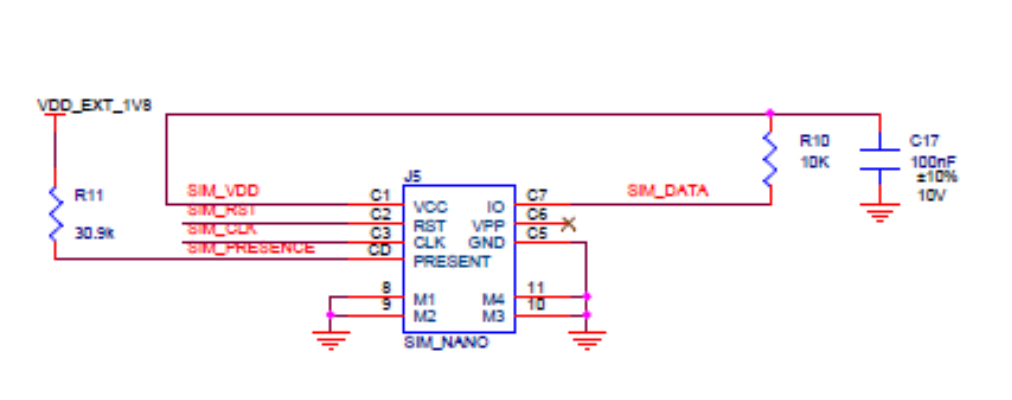
You can check the solder points:
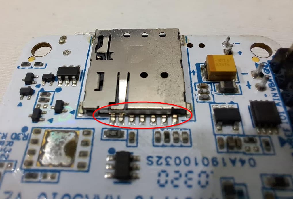
You can check whether SIM_VDD is available (1.8V)
You can check if SIM_PRESENCE goes to GND when the card is inserted.
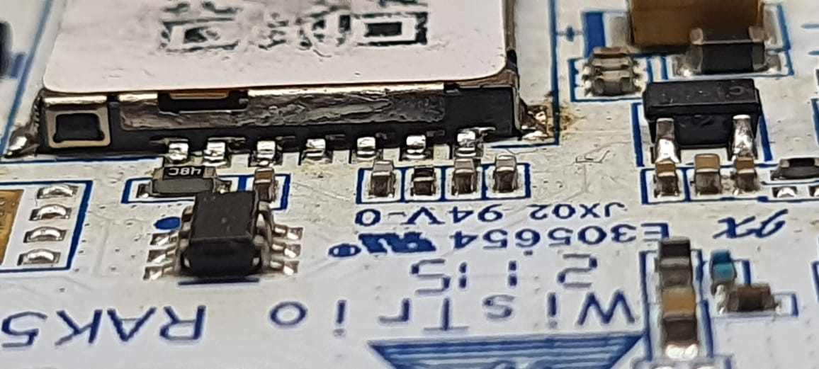
It could as well be that the contacts inside the holder are disformed or dirty.
This is how RAK module at our place is looking like… Even I am feeling that pins are displaced. What I am assuming is right or wrong please let me know
We measured voltages using multimeter too. At SIM_VDD pin observed 1.797V. Remaining all pins are almost 0V.
Nothing, seems you RAK5010 has a problem.
If you bought the device directly from RAKwireless Store, kindly send an email to [email protected] if you device is within warranty period and ask for replacement.
If you bought the device from a reseller, please contact the reseller.
@ beegee, thank you.
Check your network coverage to ensure that you are in an area with strong airtel network reception. if you have confirmed that the sim card is inserted correctly and compatible and the issue persists, there might be a hardware problem with sim card slot or the device’s cellular module.