My PPK2 gives me all sorts of options both in the application window & for export of data running to hours, or if I sample too fast, hundred of minutes.
I know this doesn’t necessarily help get the current down, but it’s so much easier to debug if you have a full picture.
@nmcc great point, I’ll see about getting a longer capture to see if it clears things up, however I think even with the 52ms window after waiting >30s, with a very low trigger threshold, I should still be getting an accurate average reading.
@beegee Thank you again for your responses. Unfortunately, U2 is indeed empty and unpopulated. I greatly wish I could get down to at most 120uA, that would be sufficient for the future projects I had in mind I believe. Is there any chance you could provide the sketch you used to get that value, or better yet, the sketch and compiled .hex file? Then we could compare apples to apples and make sure there isn’t something else going on.
This is all in the name of discovery for our product line that would use the WisBlock Core for hundreds of devices if this prototype shows promise, so anything you could do to help make that a reality would be appreciated.
Not for the sleep if you’ve got that 5mA spike in it - it will distort the average considerably.
Overall the silicon manufacturers are in some bizarre arms race of low current mode in the same way everyone likes to boast about the GHz their CPUs run at - it wouldn’t surprise me if we had a Volkswagen style scandal come up at some point about someone rigging their results via some bizarre mode they built in behind the scenes.
I’ve just done a project where the Rx1 delay time on TTS v3 (now at 5s) turned out to be using 20% of the overall battery consumption. So we concentrated on that as it was a waste to leave the MCU running at full speed twiddling its thumbs.
But rather than shooting for the moon, what’s the use case, what power source will you have? I’m happy to help with the calcs on battery life.
Thank you both again for sticking with this, don’t give up on me!
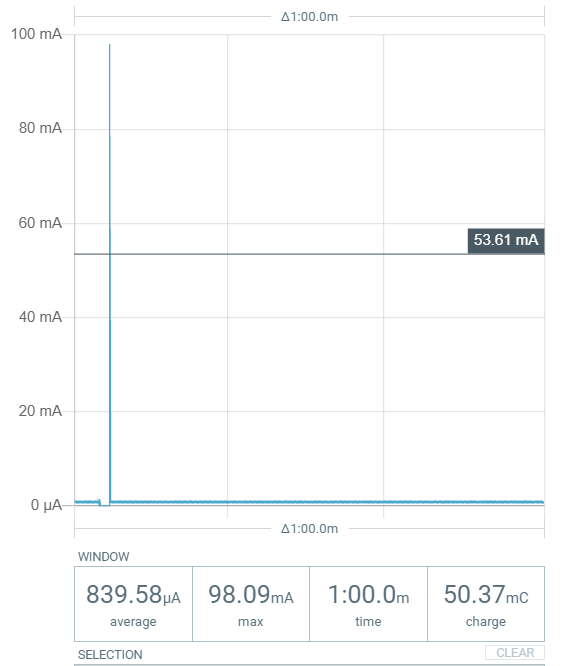
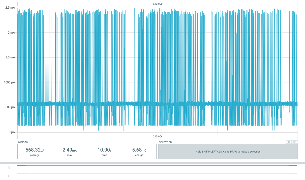
I uploaded LoRa-DeepSleep-Ard, uncommented #define TX_ONLY, and uploaded it to the board. I then removed the USB from the board.
Then, while powering the board via the PPK2 at 3.3V using the Core’s header pins I captured roughly 30s of data (downloadable here), enough to see 4 TX current peaks and plenty of sleep time in between. To summarize the data, over the ~30s period the average current is 888uA, with a minimum sleep current of 557.8uA. Letting the setup run over a longer period of time (several minutes, with 1 minute FIFO), the average current does not improve, hovering around 840uA average over a 60s window, with minimum currents of ~475uA.
With Enable DUT power output off, the PPK2 reads an average of ~40nA, just FYI.
The use case in mind is a generic sensor node that can be configured to use various sensors, with various sensor polling and LoRaWAN reporting times running on a large non-rechargeable lithium-based battery, intended to last multiple years in the field. The device would utilize the RAK4631 core, with a custom base to do this.
Once we solve this current issue (if it can be solved) I’d definitely greatly appreciate your help with battery life calculations later on.
I agree, developing a base PCB to implement the peripherals I want while remaining low power is certainly a feat in and of itself, which is why I’m really trying to nail down expectations now.
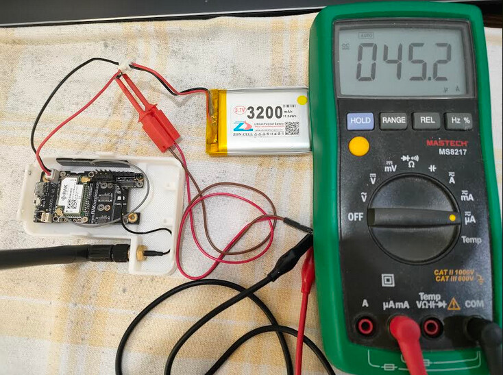
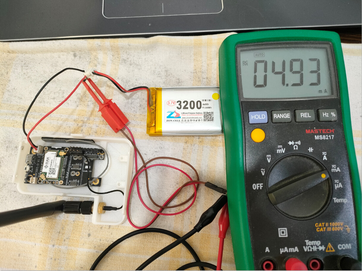
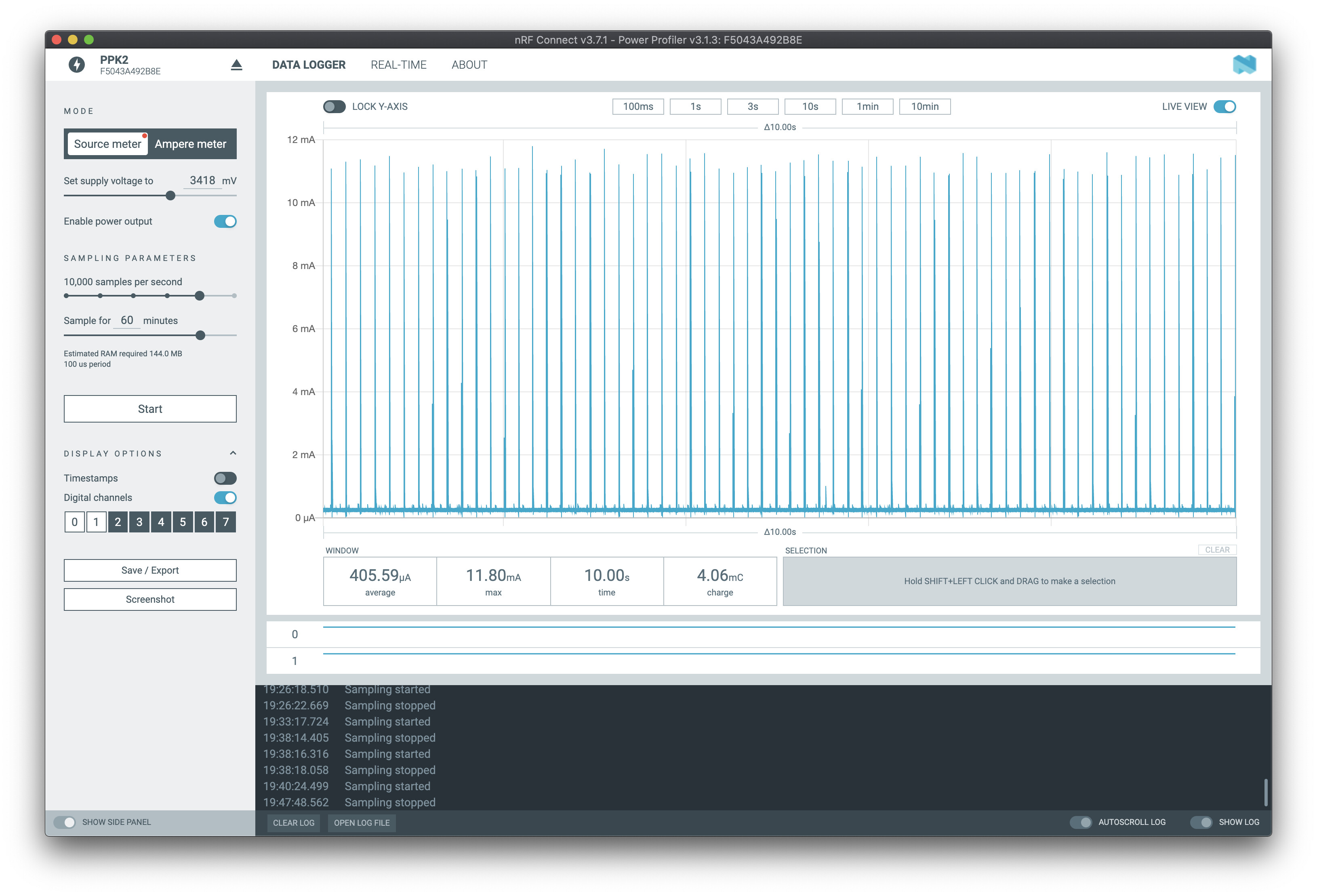
So far I’ve been reporting values for the starter kit (core + base), powered off of the core’s 3V3 and GND pins with the PPK2 at 3300mV. When I try to power just the core (detached from the base) using the same sketch without reuploading, I don’t see the LoRa functionality or any other peaks aside from the startup current peak. (see below). Am I doing something wrong? Please let me know if I should make another thread for this.
Not sure what exactly the problem with your WisBlock is.
Just two thoughts:
Did you try to power the module over the battery connector (like I showed here)? Because you are sourcing the system on the wrong side of the power regulators and I am not sure what leakage you can get with it.
Running the RAK4631 without the base board, just supplying with 3.3V should work, but to be honest, I never tried it. I will give it a try later today.
Disregard and do not setup the power supply of the RAK4631 as shown below. It is not safe to use it.
The RAK4631 is designed to work with a WisBlock Base Board only and needs VBat and 3.3V supply to work correct.
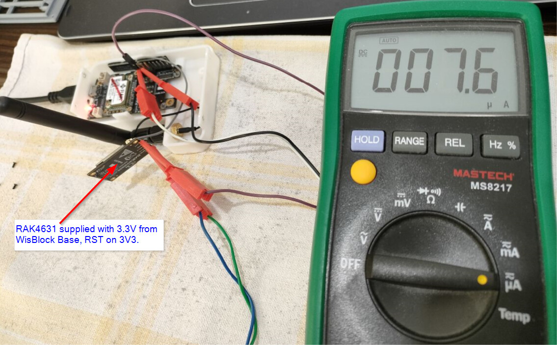
About running the RAK4631 without the base board. I just tested it and it works just fine.
Required connections:
3.3V, GND (obvious) and RST pulled to 3V3.
RST is not pulled up inside the RAK4631, so without pulling it up, the MCU doesn’t start.
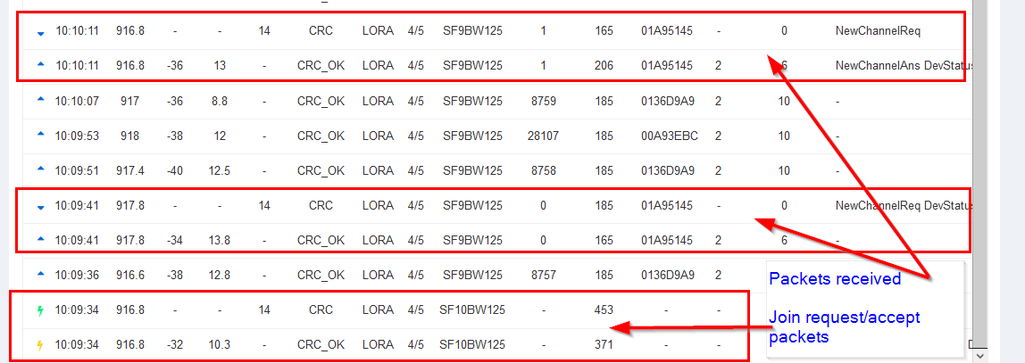
I tested a new firmware for low power consumption that connects to LoRaWAN server. So it is not like LoRa P2P.
Getting ~7.6 uA when running the RAK4631 separate from the Base board. LoRaWAN join and packet sending works:
This is definitely in the good enough zone to crack on - there may be some optimisations to do with disabling the serial and other peripherals on the MCU, but that’s definitely in the zone.
To put it in context on doing low power on a board with ‘bits’ on, the best I can squeeze out of an Arduino MKR WAN 1310 is 13uA after I’ve detached all the voltage reg / battery charger etc circuitry.
If you need a voltage regulator to cap any over zealous batteries, I use the MCP1703 from Microchip - adds just 2uA to a sleeping device and is cheap & easy to implement.
Further context, the self-discharge of good Alkaline AA batteries is ~10uA.
That’s fantastic! Running my own experiment using the same plain-LoRa TX only send sketch as before but with RST pulled high this time led to a sleep current of ~16.5uA! Exciting stuff, truly. As nmcc said it seems the core will be sufficient for projects moving forward.
@beegee could you please let me know the low power sketch you’re using for LoRaWAN? I’ll need to tackle that soon for the final application I’m developing.
After that, I’ll start tackling getting ultra low power using BLE as well. Any tips there would be appreciated, though I might make another thread for that.
Thank you so much for your help everyone, if I hit another wall I’ll be sure to reach out again. Likewise @nmcc I’ll let you know when I could start using battery estimations, thank you again for your offer there as well.
@cmod
Documentation is far from complete, but I put the code I used during the power measurements in my Github repo
It is for sure not a simple and easy to understand code, but it tries to have LoRaWAN and BLE standardized (like an API) so that the user can concentrate on the main application.
@beegee Thank you! Seems like an excellent framework, looking forward to giving this a shot. If you’d like, I can return with some current measurements using that code here, or send them to you some other way if you’re interested.
Hi @beegee first all, thanks for Wisblock API, I’m currently in progress to integrate it to my project. Looks promising.
My message is about power consumption. Similar to @cmod I got
My test code is very simple, no LoRa task, just BLE advertising, and then idle. Yet, during idle I got >500uA current consumption on average. So, far below your 40-ish uA.
#include <Arduino.h>
#include <Wire.h>

#define API_DEBUG   1
#include <WisBlock-API.h>

// Just logging library, nothing special
#include "AppLog.h"
#undef LOG_GROUP
#define LOG_GROUP "MAIN"

char g_ble_dev_name[10] = "ST-GNSS";

void setup_app() {
    Serial.begin(115200);

    time_t serial_timeout = millis();
    // On nRF52840 the USB serial is not available immediately
    while (!Serial)
    {
        if ((millis() - serial_timeout) < 5000)
        {
            delay(100);
            digitalWrite(LED_BUILTIN, !digitalRead(LED_BUILTIN));
        }
        else
        {
            break;
        }
    }
    digitalWrite(LED_BUILTIN, LOW);

    LOG_VERBOSE("App starts!");

    // Disable power for attached GNSS block
    pinMode(WB_IO2, OUTPUT);
    digitalWrite(WB_IO2, LOW);

    pinMode(WB_IO1, INPUT_PULLUP); // I don't know if this necessary

    // Enable BLE
    g_enable_ble = true;

    // Set firmware version
    api_set_version(SW_VERSION_1, SW_VERSION_2, SW_VERSION_3);
}

bool init_app() {

    Serial.end();
    return true;
}

void app_event_handler() {

    // Timer triggered event
    if ((g_task_event_type & STATUS) == STATUS) {

        // Reset
        g_task_event_type &= N_STATUS;

        LOG_VERBOSE("Timer wakeup");
    }
}

/**
   @brief Handle BLE UART data
*/
void ble_data_handler(void)
{
    if (g_enable_ble)
    {
        /**************************************************************/
        if ((g_task_event_type & BLE_DATA) == BLE_DATA)
        {
            // BLE UART data arrived
            // in this example we forward it to the AT command interpreter
            g_task_event_type &= N_BLE_DATA;

            while (g_ble_uart.available() > 0)
            {
                at_serial_input(uint8_t(g_ble_uart.read()));
                delay(5);
            }
            at_serial_input(uint8_t('\n'));
        }
    }
}

void lora_data_handler() {}
Hi @beegee thanks for responding. Sorry for just reporting back.
I did what you suggest. It’s indeed reducing current consumption, by a little. Now, it’s 405 uA.
Not sure why it’s not as your number. I’ve double checked, no LED is ON, and seems nothing to run.
I did connect accelerometer and BME680 sensor. Is it because of quotient current?
Any advice to check will be very appreciated. Thanks.
Just throwing in my experience, this is about the greatest extent in power savings I could achieve as well, wasn’t able to get it lower than this point. I didn’t try stopping and restarting the SPI bus however, this could be the trick to getting down to a more respectable 50uA.
