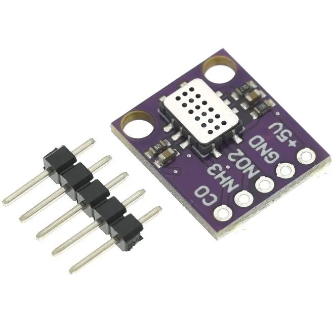
Hello, I wanted to know where I can connect this type of image sensor to my board:
I want to measure NO2, but I don’t know how to make the connections to the board and I was also wondering if I can measure all three gases at the same time, thank you very much.
For the code im using arduino in the platform IO enviroment.
sorry for my bad english.
You have to provide more details about that sensor. My guess though is that it is analog output for the 3 different gases. I doubt that it is an I2C sensor since the pins are not I2C bus (SDA and SCL).
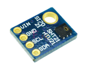
Just to illustrate, this temperature & humidity sensor is I2C since you can see the I2C serial connections (SDA and SCL) pin on the board.
Your sensor doesn’t have these pins so it is very likely NOT to be an I2C interface.
yes sorry! my mistake, its just like you see it in the image, on a normal arduino you would connect the sensor GND to the GND, the 5V to 5V and the NO2 CO and NH3 to an analog input like A0, A1 etc.
here is the link for the sensor if its of any help:
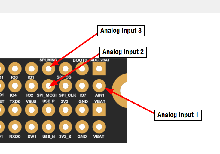
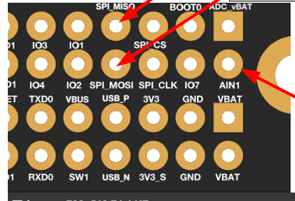
If you are using RAK19001 as baseboard and RAK4631 (Not RUI3), you can use WB_A1, WB_SPI_MOSI and WB_SPI_MOSI as analog inputs. WB_A0 is connected to VBAT so you cannot use it (unless the voltage divider on WB_A0 wont have any on the sensor readings).
Here’s a sample sketch on getting the analog reading.
#include "Wire.h"

// These constants won't change. They're used to give names to the pins used:
const int analogInPin = WB_A1;  // Analog input pin that the potentiometer is attached to
const int analogInPin2 = WB_SPI_MOSI;  // Analog input pin that the potentiometer is attached to
const int analogInPin3 = WB_SPI_MISO;  // Analog input pin that the potentiometer is attached to

int sensorValue = 0;        // value read from the pot
int sensorValue2 = 0;        // value read from the pot
int sensorValue3 = 0;        // value read from the pot

void setup() {
  // initialize serial communications at 9600 bps:
  Serial.begin(9600);
}

void loop() {
  // read the analog in value:
  sensorValue = analogRead(analogInPin);
  sensorValue2 = analogRead(analogInPin2);
  sensorValue3 = analogRead(analogInPin3);

  // print the results to the Serial Monitor:
  Serial.print("sensor = ");
  Serial.print(sensorValue);
  Serial.print(" sensor2 = ");
  Serial.print(sensorValue2);
  Serial.print(" sensor3 = ");
  Serial.println(sensorValue3);

  // wait 500 milliseconds before the next loop for the analog-to-digital
  // converter to settle after the last reading:
  delay(500);
}
You also have the option to use the WisBlock ADC module RAK16001. This can give you more reliable readings than the built-in ADC. Of course, it still depends on your preference.
i also wanted to ask you if my sensor needed 5V is there any inputs for that or i just have to use the 3.3V?
Thank you so so much for your patience and your time.
I cant use the RAK16001 because im already using the two IO slots for other things, but if i wanted to use it, would i have to use the V and the GND from this section as well?