I´m developing on Arduino.
Everithing goes well when connected to PC vía USB.
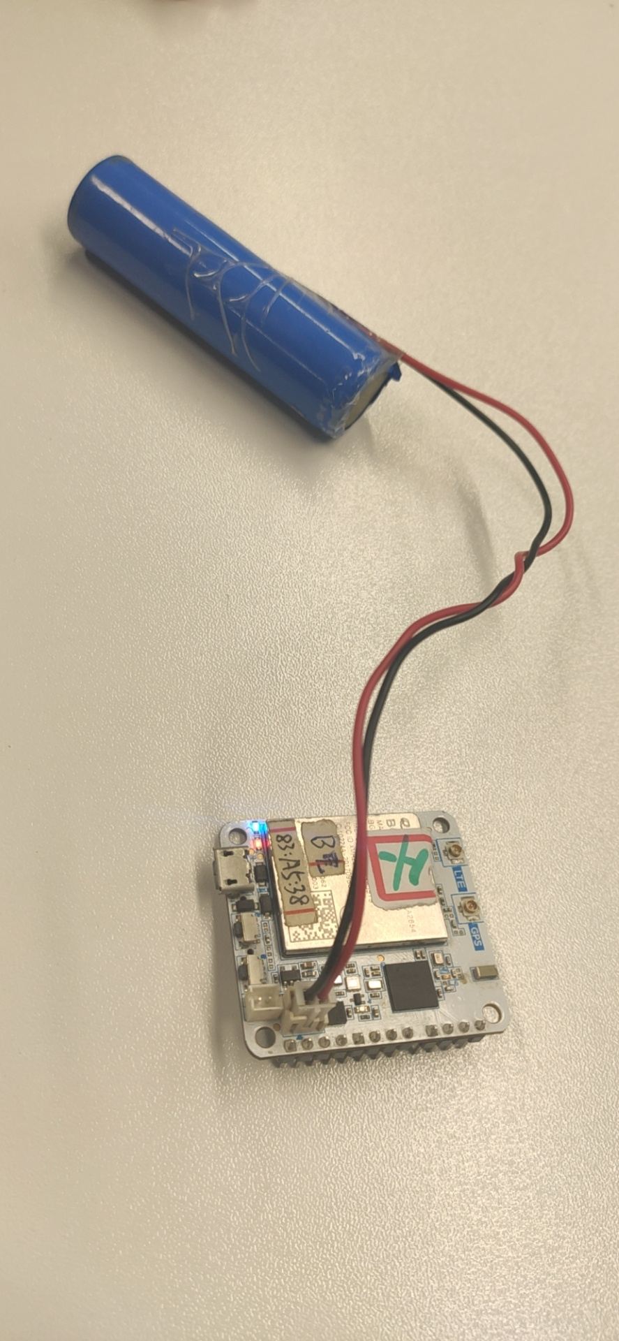
When I power the board using a simple USB charger or/and a 3.7V LI-Ion battery, the board doesn’t boot (I think because no led´s).
With default firmware, same battery it, hasn’t got a problem.
Hi,
What the default firmware do you use? I’am not clear what board doesn’t boot mean. If you download the bootloader from our github, it must be show the usb com port.
ok, I see. Because our default firmware is optimized. It has the good performence on 5010. But about Arduino, we just run it successfully without optimized. We will optimize it later. It is great if you can develop it on RAK5010 based our work.
Hi,
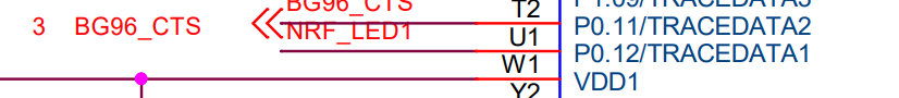
According to the code of adafruit, P11 is for DFU and P12 is for FRST. I’ve checked the layout of 5010. They are like this. P11 is for UART CTS of BG96, P12 is for LED.
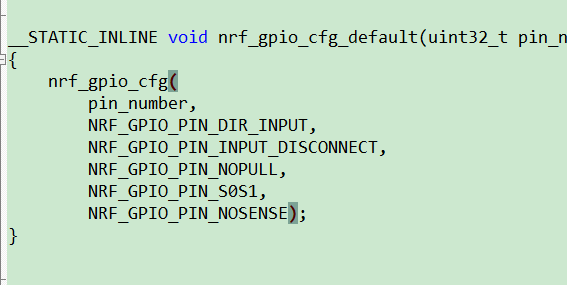
But in our demo, we do not use these two pin. They should be default state. According to nordic SDK, they should be:
So if you want to use DFU funtion, I advise you change the Pin num in code of adafruit, point to the rest pin for user. Like IO1 to IO4. But remember, the four pins is useful unless input 3V3 to Vref closed IO1~IO4.
The intention is not using DFU, instead is to solve the boot to application code when power the board using a battery only.
Changing adafruit bootloader is not suitable, because of maintennance. What I need is to get P11 and P12 on HIGH always, but I think is impossible due to the layout of 5010.
I can conclude that using Adafruit bootloader is only possible when connected to PC USB.
Right?
Thanks
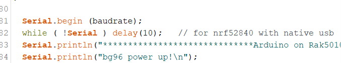
I have test, it can be powered with battery only without any problem. In the setup, you just need delete the “While (! Serial) delay(10)” and add just “delay(1000)”. Because it waits for a usb connection forever.