A low power consumption firmware for RAK811!

hi, all

I have measured 21uA sleep current on Wisnode Lora RAK811 board.
v3.0.0.12.H
at+set_config=device:sleep:1

( Removed 0R resistor, removed the next jumper, wired ampermeter between this jumper pins. Yes this measured LVCC_3V3 line which powering only module)

There is something strange.

Yes I measure 21uA sleep current on Wisnode LoRa RAK811 board v3.0.0.12.H.

On the other hand;
I have made my own board using RAK811 smd module with a connection to a host microcontroller. Sending AT commands from host to RAK811.
Version is same v3.0.0.12.H, Configuration is same.
AT command: at+set_config=device:sleep:1

My RAK811 circuit is identical to the Wisnode Lora Board.
But, I have measured about 100uA sleep current. That is far more than on the original board.
I have checked all the things related to power consumption.

Why ?
Does different modules make sense ?

I have a ftdi232 usb to serial converter. I have connected a RAK811 breakout board as following
FDTI232 GND <----------------------------------->RAK811 GND
FDTI232 Tx <------------------------------------>RAK811 Rx
FDTI232 Rx <------------------------------------>RAK811 Tx
FTDI232 3.3V <------Ammeter(Fluke177)---->RAK811 VCC
All other pins are not connected to anywhere

Now using cutecom I sent the following commands

at+version
Firmware Version: RUI v3.0.0.12.H
OK
at+join
OTAA:
DevEui:****************
AppEui:****************
AppKey:**************************************
OTAA Join Start…
[LoRa]:Join Success
OK
at+get_config=lora:status
OK.


==============LoRaWAN Status List================
Work Mode: LoRaWAN
Region: AS923
Send_interval: 600s
Auto send status: false.
Join_mode: OTAA
DevEui: **********************
AppEui: **********************
AppKey: *******************************************
Class: A
Joined Network:true
IsConfirm: false
AdrEnable: true
EnableRepeaterSupport: false
RX2_CHANNEL_FREQUENCY: 923200000, RX2_CHANNEL_DR:2
RX_WINDOW_DURATION: 3
000ms
RECEIVE_DELAY_1: 1000ms
RECEIVE_DELAY_2: 2000ms
JOIN_ACCEPT_DELAY_1: 5000ms
JOIN_ACCEPT_DELAY_2: 6000ms
Current Datarate: 2
Primeval Datarate: 2
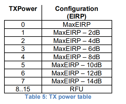
ChannelsTxPower: 0
UpLinkCounter: 0
DownLinkCounter: 0
===================List End======================


at+set_config=device:sleep:1
Go to Sleep.

Fluke177 can measure current two digits after decimal in mA. So At the start I see around 5.88mA current consumption. When I send the sleep command it reduces to 0.09mA which is far more than 10.3uA current consumption. I have also tried it with firmware 3.0.0.8H. It also consumes 0.09mA. But firmware 3.0.0.4 gives good result. So if my way of measuring current consumption is correct, something bug fixing for firmwares between 3.0.0.4H~3.0.0.8H introduced this problem.

If you can reproduce it and consider it as a bug, please let us know. We can keep our hands crossed until another new firmware with the bug fix is released.

Hi @leanofis,

Yes, we found this power consumption issue in the latest firmware too, and we’ve fixed it today.
We’ll upload the new firmware on our web site tomorrow.

Hi @Fomi ,

To solve power consumption issue;
Is this version firmware ?

https://downloads.rakwireless.com/en/LoRa/RAK811/Firmware/RUI_RAK811_V3.0.0.12.H.T_Release.rar

( and new bootloader )
https://downloads.rakwireless.com/en/LoRa/RAK811/Firmware/RUI_RAK811_BOOT_Version3_0_2.rar

Hi,@leanofis
yes,that 's right.

Hi @leopold @Fomi

I did upgrade versions to bootloader(3.0.2) and firmware(3.0.0.12.H.T).

Now, Sleep current is les than 10uA.

This is wonderful, thank you so much.

Hi,@alen
Please upgrade firmware to RUI_RAK811_V3.0.0.12.H.T_Release :
https://downloads.rakwireless.com/en/LoRa/RAK811/Firmware/RUI_RAK811_V3.0.0.12.H.T_Release.rar

with new bootloader :
https://downloads.rakwireless.com/en/LoRa/RAK811/Firmware/RUI_RAK811_BOOT_Version3_0_2.rar

Hi @leopold @Fomi ,

According to EU868, max EIRP is 16dbm.
at+set_config=lora:tx_power:0

How to test 20dbm on RAK811?
Any AT command available ?

The following figure shows the power corresponding to EU868.
image
20dbm May not be supported in EU868 band, maybe you can try other band.

Next time I will compare range for RAK811 (High frequency) to RAK7258,
With minimum datarates;
TTN

EU868 16dbm SF12BW125
US902 20dbm SF10BW125
AU915 20dbm SF10BW125
IN865 20dbm SF12BW125 (3 channel)

now, i am using RAK811 module, and use it for water meter reading application.
in RUI API, is there any option to select numerous low power modes in STM32L1xx ?

Hi @mamanbudiman,

You can use the following RUI API to set RAK811 module sleep or wake up:

RUI_RETURN_STATUS rui_device_sleep(uint32_t on)
0: wake up. 1: sleep

Hi @Fomi, It’s great post.
Could you please update the keil code at RAK github page ?https://github.com/RAKWireless/RAK811_LoRaNode

I used that code to create some customized lora sensornode, everything was working fine until it came into sleep mode, it seemed the device not waking up. here is my code for sleep mode:

RtcSetTimeout(60000);
SX1276SetSleep();
SX1276Write(REG_OPMODE,SX1276Read(REG_OPMODE)& 0xF8);
__HAL_RCC_RTC_DISABLE();
    __HAL_RCC_LSE_CONFIG(RCC_LSE_OFF);
BoardDeInitMcu();
SysEnterUltraPowerStopMode();
DelayMs(10);

BoardInitMcu();
__HAL_RCC_LSE_CONFIG(RCC_LSE_ON);
    __HAL_RCC_RTC_ENABLE();
SX127X_INIT();
GPIOIRQ_Enable();
rw_LoadUsrConfig();

from debugging mode, after mcu entered sleep mode, when rtc interrupt occured, it goes to the end of function ( i set a breakpoint there). then i try to join OTAA - again, or sending some payload to loraserver. but nothing accepted by the server or rak811 send nothing.
what actually is the problem?
I need this low-power/sleep mode in my device, or the battery power will drain fast.

Hi @dadanugm
you could update and try these functions

void InstallWakeUpPin(void)
{
	uint32_t temp;
	uint32_t iocurrent;
	/* Enable SYSCFG Clock */
	__HAL_RCC_SYSCFG_CLK_ENABLE();
	iocurrent = (GPIO_PIN_10) & ((uint32_t)1 << 10);
	temp = SYSCFG->EXTICR[10 >> 2];
	CLEAR_BIT(temp, ((uint32_t)0x0F) << (4 * (10 & 0x03)));
	SET_BIT(temp, (GPIO_GET_INDEX(GPIOA)) << (4 * (10 & 0x03)));
	SYSCFG->EXTICR[10 >> 2] = temp;

	/* Clear EXTI line configuration */
	temp = EXTI->IMR;
	CLEAR_BIT(temp, (uint32_t)iocurrent);

	SET_BIT(temp, iocurrent); 

	EXTI->IMR = temp;

	temp = EXTI->EMR;
	CLEAR_BIT(temp, (uint32_t)iocurrent);      

	EXTI->EMR = temp;

	/* Clear Rising Falling edge configuration */
	temp = EXTI->RTSR;
	CLEAR_BIT(temp, (uint32_t)iocurrent); 

	SET_BIT(temp, iocurrent); 

	EXTI->RTSR = temp;

	temp = EXTI->FTSR;
	CLEAR_BIT(temp, (uint32_t)iocurrent); 

	SET_BIT(temp, iocurrent); 

	EXTI->FTSR = temp;
}

void UninstallWakeUpPin(void)
{
	uint32_t tmp = SYSCFG->EXTICR[10 >> 2];
	uint32_t iocurrent = (GPIO_PIN_10) & ((uint32_t)1 << 10);

	tmp &= (((uint32_t)0x0F) << (4 * (10 & 0x03)));
	if(tmp == (GPIO_GET_INDEX(GPIOA) << (4 * (10 & 0x03))))
	{
		tmp = ((uint32_t)0x0F) << (4 * (10 & 0x03));
		CLEAR_BIT(SYSCFG->EXTICR[10 >> 2], tmp); 
		/* Clear EXTI line configuration */
		CLEAR_BIT(EXTI->IMR, (uint32_t)iocurrent);
		CLEAR_BIT(EXTI->EMR, (uint32_t)iocurrent);
		/* Clear Rising Falling edge configuration */
		CLEAR_BIT(EXTI->RTSR, (uint32_t)iocurrent);
		CLEAR_BIT(EXTI->FTSR, (uint32_t)iocurrent);        
	} 
}

void SysEnterUltraPowerStopMode( void )
{
	InstallWakeUpPin();

	// Disable the Power Voltage Detector
	HAL_PWR_DisablePVD( );

	SET_BIT( PWR->CR, PWR_CR_CWUF );

	// Enable Ultra low power mode
	HAL_PWREx_EnableUltraLowPower( );

	// Enable the fast wake up from Ultra low power mode
	HAL_PWREx_EnableFastWakeUp( );

	// Enter Stop Mode
	HAL_PWR_EnterSTOPMode( PWR_LOWPOWERREGULATOR_ON, PWR_STOPENTRY_WFI );

	__HAL_PWR_CLEAR_FLAG( PWR_FLAG_WU );

	SystemClockReConfig();

	UninstallWakeUpPin();

	GpioWrite( &Xtal, 1 );
}

void SystemClockReConfig( void )
{
    __HAL_RCC_PWR_CLK_ENABLE( );
    __HAL_PWR_VOLTAGESCALING_CONFIG( PWR_REGULATOR_VOLTAGE_SCALE2 );

    /* Enable HSI */
    __HAL_RCC_HSI_ENABLE();
    /* Wait till HSE is ready */
    while( __HAL_RCC_GET_FLAG( RCC_FLAG_HSIRDY ) == RESET )
    {
    }

    /* Select PLL as system clock source */
    __HAL_RCC_SYSCLK_CONFIG ( RCC_SYSCLKSOURCE_HSI );

    /* Wait till PLL is used as system clock source */
    while( __HAL_RCC_GET_SYSCLK_SOURCE( ) != RCC_SYSCLKSOURCE_STATUS_HSI )
    {
    }
}

hi @leopold, thanks for the answer.
I’ve changed my code with your code, it seems your code is exactly same with the code in compiler,
the different is only at GpioWrite( &Xtal, 1 ); <-- in SysEnterUltraPowerStopMode
in my code is GpioWrite(&SX1276.Xtal, 1 );
since there is no object name Xtal.
so it gives the same result as previous one. no uplink data after sleep and wakeup :slight_smile:

Hi @dadanugm

Hope the following points can help you.

  1. First, determine if RAK811 really enters sleep state, and what is its sleep current
    2.stm32 enters stop mode. It is not recommended to use debug mode. Use serial port to print LOG for debugging.
  2. Generally, when the RAK811 does not work after waking up, it is necessary to check whether the master clock is correctly configured, to check whether the SPI is re-enabled and whether the interrupt is enabled.
    4.GpioWrite (& SX1276.Xtal, 1) means to open the power supply pin of SX1276, because the crystal power supply needs to be turned off before entering the low power mode. If the compilation fails, you can directly pull up the PH_1 pin.
    5.Remove __HAL_RCC_RTC_DISABLE () in code that goes into low power consumption;

HI @Daniel, thanks for the advices

  1. It was entering sleep mode, the current about 36uA
  2. How to check the master clock is correctly configured when the module is shielded, does that mean I have to open the shield?
      1. Ok, I’ll try that

Hi @dadanugm
The main frequency can only check the code at present. The main frequency mainly affects the speed of SPI. If the main frequency is incorrect, MUC will not be able to operate SX1276 through SPI.