I’m considering working with the RAK11160 but not using the RUI3. Instead, I plan to use the STM32 and ESP32C2 with their base firmwares.
I’ve already managed to flash both. I loaded the BLE AT firmware provided by espressif onto the ESP32C2, but I’m having problems sending and receiving AT commands.
STM32WLE5 Name STM32WLE5 Pin ESP32-C2 Name ESP32-C2 Pin Function
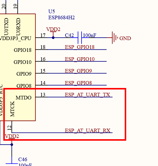
UART TX PA2 UART RX MTCK/GPIO6 UART
UART RX PA3 UART TX MTDO/GPIO7 UART
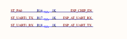
Enable PA0 CHIP_EN CHIP_EN ESP32-C2 enable
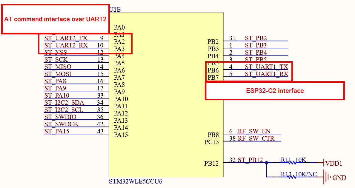
According to the guide, USART2 is connected to pins 6 and 7 of the ESP32C2. I sent “AT\r\n” through USART2 and received no response from the ESP32C2.
I saw in one of the posts that @carlrowan mentions that the AT commands for the ESP32C2 go to USART1. I also tried sending the AT commands through PB6 and PB7, but there’s no response either.
Which STM32 pins does the ESP32C2’s USART connect to? Which STM32 USART does it correspond to?
If it is indeed on USART2 PA2 and PA3, how do they use USART2 for both AT commands and printf?
The pins are not correct - PA2 PB6 to GPIO6 (MTCK) and PA3 PB7 to GPIO7 (MTDO). Then you have to enable it via PA0.
If you are still using the default RUI3 FW of RAK11160 but with BLE AT command for ESP32-C2, you just enable the passthru mode AT+ESP=1. This way, the AT commands that you send to UART2 will be directed directly to the ESP32-C2.
Actually, I’m no longer using the RUI3; I’m using the STM32cube IDE. Regarding that, what I did was configure PA0 to HIGH and USART2 to PA2 and PA3. I sent an “AT\r\n” command and received no response.
I also tried connecting the FTDI to the PA2 and PA3 lines without crossing them (since they are internally crossed) and sending commands with the serial monitor, but it didn’t respond either.
I also tried setting the STM32 with PA2 and PA3 as pull-up inputs to prevent it from setting the GPIOs to HIGH or LOW, but that didn’t work either.
I flashed the ESP32C2 with the BLE AT commands, and this is what the ESP32C2 serial debug monitor shows.
d8f2-dirty 2nd stage bootloader
17:54:15:581 → I (32) boot: compile time Mar 27 2026 03:42:01
17:54:15:586 → I (32) boot: chip revision: v1.2
17:54:15:589 → I (34) boot: efuse block revision: v0.1
17:54:15:592 → I (38) boot.esp32c2: MMU Page Size : 32K
17:54:15:595 → I (41) boot.esp32c2: SPI Speed : 60MHz
17:54:15:600 → I (45) boot.esp32c2: SPI Mode : DIO
17:54:15:603 → I (49) boot.esp32c2: SPI Flash Size : 2MB
17:54:15:609 → I (53) boot: Enabling RNG early entropy source…
17:54:15:611 → I (57) boot: Partition Table:
17:54:15:614 → I (60) boot: ## Label Usage Type ST Offset Length
17:54:15:620 → I (66) boot: 0 otadata OTA data 01 00 00009000 00002000
17:54:15:628 → I (73) boot: 1 phy_init RF data 01 01 0000b000 00001000
17:54:15:634 → I (79) boot: 2 nvs WiFi data 01 02 0000c000 0000e000
17:54:15:639 → I (86) boot: 3 at_customize unknown 40 00 0001a000 00010000
17:54:15:648 → I (92) boot: 4 storage Unknown data 01 22 0002a000 000a6000
17:54:15:653 → I (99) boot: 5 ota_0 OTA app 00 10 000d0000 00130000
17:54:15:659 → I (105) boot: End of partition table
17:54:15:664 → I (109) esp_image: segment 0: paddr=000d0020 vaddr=3c0a8020 size=1c4f4h (115956) map
17:54:15:687 → I (142) esp_image: segment 1: paddr=000ec51c vaddr=3fcadcf0 size=00210h ( 528) load
17:54:15:692 → I (143) esp_image: segment 2: paddr=000ec734 vaddr=3fcb0198 size=01888h ( 6280) load
17:54:15:701 → I (148) esp_image: segment 3: paddr=000edfc4 vaddr=40380000 size=02054h ( 8276) load
17:54:15:709 → I (156) esp_image: segment 4: paddr=000f0020 vaddr=42000020 size=a1628h (661032) map
17:54:15:854 → I (309) esp_image: segment 5: paddr=00191650 vaddr=40382054 size=05e54h ( 24148) load
17:54:15:859 → I (315) esp_image: segment 6: paddr=001974ac vaddr=40387eb0 size=05e40h ( 24128) load
17:54:15:869 → I (326) boot: Loaded app from partition at offset 0xd0000
17:54:15:874 → I (326) boot: Disabling RNG early entropy source…
17:54:16:600 → I (1116) at-init: at param mode: 1
17:54:16:603 → I (1120) at-uart: AT cmd port:uart1 tx:7 rx:6 cts:5 rts:4 baudrate:115200
17:54:16:608 → I (1121) at-init: module_name: ESP32C2-2MB-BLE
17:54:16:611 → I (1121) at-init: v4.2.0.0-dev (GitHub - espressif/esp-at: AT application for ESP32/ESP32-C2/ESP32-C3/ESP32-C6/ESP8266 · GitHub)
I never used the RAK11600 without the default firmware (for both SYM32 and ESP32).
According to the internal schematics PA2 TX / PA3 RX are for RUI3 AT commands and PB6 TX / PB7 RX are for the connection to the ESP32-C2: