I’m using a RAK4631 to read data from a LIS3DH accelerometer and buffer it to do some calculations later. The sampling rate is important because I need to measure up to 2000 Hz vibrations in this application.
This accelerometer promises 5 kHz ODR but in my tests I can only get a maximum of around 1700 Hz when using only 1 axis!!! and 500 when using the 3 of them. I’ve even tried to play with the registers to maximize data rate, activating the Low Power Mode in CTRL_REG_1 and disabling High Resolution in CTRL_REG_4.
For now to measure the data rate I created a counter function that just count the loops in 1 seconds, I would appreciate if someone knows a better way to do this. And of course for the tests I have commented every Serial.print.
If someone has or had the same problem or knows a solution for the low data rate it would save my life.
I will drop my code below.
Thanks a lot
#include <Arduino.h>
#include "SparkFunLIS3DH.h"
#include "Wire.h"
#include "SPI.h"

LIS3DH myIMU(I2C_MODE, 0x18); //Default constructor is I2C, addr 0x19.

#define BUFFER_SIZE 4096
char dataBuffer[BUFFER_SIZE];
unsigned int bufferIndex = 0;

unsigned long lastMillis = 0;
unsigned long count = 0;

#define SAMPLE_BUFFER_LENGTH        4096
#define SAMPLE_BUFFER_LENGTH_HALF   (SAMPLE_BUFFER_LENGTH/2)
#define SAMPLING_RATE               5000
float fft_input_x[SAMPLE_BUFFER_LENGTH];
float fft_input_y[SAMPLE_BUFFER_LENGTH];
float fft_input_z[SAMPLE_BUFFER_LENGTH];

void counter(){
  unsigned long currentMillis = millis();

  count++;

  if (currentMillis - lastMillis >= 1000) {
    // Muestra el contador cada segundo
    Serial.print("Counter: ");
    Serial.println(count);

    count = 0;
    lastMillis = currentMillis;
  }
}

void accelConfig(){
  myIMU.settings.adcEnabled = 0;
  myIMU.settings.tempEnabled = 0;
  // myIMU.settings.accelSampleRate = 5000;  //Hz.  Can be: 0,1,10,25,50,100,200,400,1600,5000 Hz
  // myIMU.settings.accelRange = 8;      //Max G force readable.  Can be: 2, 4, 8, 16
  // myIMU.settings.xAccelEnabled = 1;
  // myIMU.settings.yAccelEnabled = 1;
  // myIMU.settings.zAccelEnabled = 1;
}

void setup() {

  Serial.begin(9600);

  accelConfig();
  myIMU.begin();  //Call .begin() to configure the IMU
  myIMU.writeRegister(LIS3DH_CTRL_REG1, 0x9F); //MANUAL LOW-POWER MODE ENABLE / 5376 KHZ ODR
  myIMU.writeRegister(LIS3DH_CTRL_REG4, 0xA0); //MANUAL HIGH RESOLUTION OFF / SCALE +-8G

  delay(1000);
  Serial.println("Processor came out of reset.\n");
}

void loop() {
  unsigned long startTime = millis();

  for (int i = 0; i < SAMPLE_BUFFER_LENGTH; i++) {
    float x_axis = myIMU.readFloatAccelX();
    fft_input_x[i] = x_axis;  //DOMINIO DEL TIEMPO

    float y_axis = myIMU.readFloatAccelY();
    fft_input_y[i] = y_axis;  //DOMINIO DEL TIEMPO

    float z_axis = myIMU.readFloatAccelZ();
    fft_input_z[i] = z_axis;  //DOMINIO DEL TIEMPO

    counter();
  }
  unsigned long endTime = millis();
  unsigned long duracion = endTime - startTime;
  Serial.print("3 Buffer filling time: "); Serial.print(duracion);

  // for(int i = 0; i < SAMPLE_BUFFER_LENGTH; i++){
  // Serial.print("EJE X: "); Serial.println(fft_input_x[i]);
  // }
  // delay(500);
  // for(int i = 0; i < SAMPLE_BUFFER_LENGTH; i++){
  //   Serial.print("EJE Y: "); Serial.println(fft_input_y[i]);
  // }
  // delay(500);
  // for(int i = 0; i < SAMPLE_BUFFER_LENGTH; i++){
  //   Serial.print("EJE Z: "); Serial.println(fft_input_z[i]);
  // }
  // delay(500);

  delay(5000);
}
Hello! I have not worked with the sensor in this mode, but I have some experience in setting up other sensors for high speed =)
Perhaps you should first set the Wire bus to the required clock frequency for the purity of the experiment.
  // Increase I2C clock speed to 400kHz to cope with the high navigation rate
  // (We normally recommend running the bus at 100kHz)
  Wire.setClock(400000);
Among other things, just in case (this is not necessary), you can configure the serial port to high-speed mode. For example, like this.
Serial.begin(115200);
Then I would remove the counter() function from the for loop for (int i = 0; i < SAMPLE_BUFFER_LENGTH; i++)» .
It seems to me that the counter() function slows down polling of sensors and introduces unnecessary delays. I don’t quite understand how it works for you. Therefore, I would write the data to a variable and only output it after polling.
And then I would configure the sensors (I think low power mode is not the best mode?).
Pardon my bad English. Perhaps I don’t understand what results you want. Do you want to poll sensors as quickly as possible?
Int count = 0;
void loop() {

unsigned long startTime = millis();

for (int i = 0; i < SAMPLE_BUFFER_LENGTH; i++)
{
	float x_axis = myIMU.readFloatAccelX();
	fft_input_x[i] = x_axis; //DOMINIO DEL TIEMPO

	float y_axis = myIMU.readFloatAccelY();
	fft_input_y[i] = y_axis; //DOMINIO DEL TIEMPO
	float z_axis = myIMU.readFloatAccelZ();
	fft_input_z[i] = z_axis; //DOMINIO DEL TIEMPO
// I think this function is not needed here?
// counter();
	count ++;
	}
	Serial.println("Counter: ");
	Serial.println(count);
        count  = 0;
	delay(5000);
}
Tomorrow I’ll try the changes in I2C clock speed, baud rate and removing the counter and get back here.
In the LIS3DH datasheet they refer to “Low-power-mode” as a mode that outputs 8-bit data instead of 12-bit, so that it is faster, they also say that the only way to obtain 5kHz ODR is with this mode enabled, so 8 bit data. The name implies as if it were slower but it isn’t.
And yes you are right, my idea is to poll the 3 axes of the accelerometer as fast as the RAK4630 and LIS3DH possibly can.
PS: Your english is fine, I’m from Chile so mine is a little broken too .
I looked at the sparkfun/LIS3DH_Breakout library code and found that the library has faster functions than myIMU.readFloatAccelX(), myIMU.readFloatAccelX() & etc
For example, the function myIMU.readFloatAccelX() and others contain another function calcAccel(readRawAccelX()), which in turn reads data using readRawAccelX().
As I think, if code optimization is required and you do not want to read data directly from registers, then you can use the functions readRawAccelX(), readRawAccelY() & etc.
In this case, you will need to replace it with int16_t
This should also have a beneficial effect on code optimization.
Then I think we can write code to call on interrupts so that readRawAccel*() is called independently of the loop.
It is also possible to read data for only one second and then clear the array.
P.S. The most important thing, of course, is the initial initialization of the sensor, but I think you know how to do this in the best way.
Good luck in job!
I tried the improvements that you commented but they didn’t seem to change the adquisition speed.
I set the i2c speed to 400 kHz and did the polling with “myIMU.readRawAccelX()” functions but the time it took to fill the axis buffers was the same, maybe 10ms faster. I’m starting to think that the advertising of 5.3 kHz for this accelerometer isn’t right. What changed a lot was the RAM consumption going from 30% to 13%.
Maybe the thing I need to do is to bump up the Cortex-M4 inside the RAK4630? Any idea if that’s possible?
Also I’m new when it comes to interrupts, how could I implement one here to take the measures.
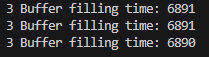
According to my code it takes 6,89 seconds to fill the 3 buffers of size 4096 (12288 points), that a looong time.
Wire.setClock(400000);
for (int i = 0; i < SAMPLE_BUFFER_LENGTH; i++) {
    int16_t x_axis = myIMU.readRawAccelX();
    fft_input_x[i] = x_axis;  //DOMINIO DEL TIEMPO

    int16_t y_axis = myIMU.readRawAccelY();
    fft_input_y[i] = y_axis;  //DOMINIO DEL TIEMPO

    int16_t z_axis = myIMU.readRawAccelZ();
    fft_input_z[i] = z_axis;  //DOMINIO DEL TIEMPO
  }

  unsigned long endTime = millis();
  unsigned long fillingTime = endTime - startTime;
  Serial.print("3 Buffer filling time: "); Serial.println(fillingTime);
I would continue experiments and not give up =)
I think we should check whether the controller can write data to the three fft_input_[] arrays with proper speed. In theory, this should not affect the speed, but…
For example, what happens if we remove three procedures fft_input_[i] = y_axis (xyz)
Will the reading speed increase if data is not written to the arrays?
That is, the idea is as follows: get rid of all operations in the sensor polling cycle and see what speed will be achievable.
If the speed does not increase, you will probably have to work directly with register polling (that is, call data directly from the program, bypassing the library).
It is also possible that the polling speeds promised by the manufacturer are only achieved when working with a powerful controller. By the way, Wisblock offers three controllers, the most powerful is a controller with two cores.
This is easy to check if you connect some available and cheap external
LIS3DH sensor to a computer (for example, this can be done with Raspberry) and “interrogate” it via i2c. Have you tried experimenting with Raspberry?

 .
.