Hello, greetings from Belgium.
I’m trying to use the IS25WP064A NOR flash that is mounted on the RAK5010 in a custom firmware that has been ported to this board to add cellular connectivity, but can’t get it to work.
To rule out any side-effects from the firmware I tried using the spi_flash sample firmware from Zephyr, but couldn’t get very far either.
My setup is quite simple:
- RAK5010 (WisTrio NB-IoT Tracker Pro PCB v2.0) connected with a J-Link programmer
- Nordic nRF Connect SDK v3.0.2 (but got the same results with 2.9.2 before upgrade)
The spi_flash firmware has been compiled and executed using the following steps:
- Open a terminal with nRF v3.0.2 profile in VSCode
- Go to the sample directory:
cd c:\ncs\v3.0.2\zephyr\samples\drivers\spi_flash - Build the sample for the RAK5010 board:
west build --pristine --board rak5010 --build-dir build_rak5010 - Program the device using
west flash --build-dir build_rak5010 --softresetin thebuild_rak5010
Here is the output on the serial console:
*** Booting nRF Connect SDK v3.0.2-89ba1294ac9b ***
*** Using Zephyr OS v4.0.99-f791c49f492c ***
is25wp064a@0: device not ready.
To get more information on why the firmware failed I enabled CONFIG_LOG in a board-specific file c:\ncs\v3.0.2\zephyr\samples\drivers\spi_flash\boards\rak5010_nrf52840.conf containing:
CONFIG_LOG=y
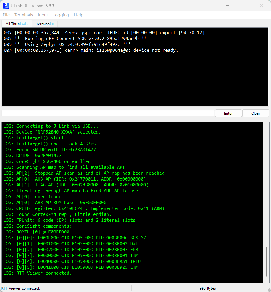
After a pristine rebuild to take this new configuration file into account I got this additional information:
[00:00:00.251,708] <err> qspi_nor: JEDEC id [00 00 00] expect [9d 70 17]
*** Booting nRF Connect SDK v3.0.2-89ba1294ac9b ***
*** Using Zephyr OS v4.0.99-f791c49f492c ***
is25wp064a@0: device not ready.
I guessed that this error occured because the qspi_rdid in zephyr\drivers\flash\nrf_qspi_nor.c was called too early after exiting the Power-down mode, but after checking the DTS it appeared that the t-exit-dpd property of the flash matched the IS25WP064A datasheet timing of tRES1 = 5µs… Another thought that after a reset we need to wait tHWRST (100µs)… So I added a 100µs delay at the beginning of qspi_init, and this allowed me to go a step further…
After a rebuild the JEDEC id of the flash was read correctly, but it failed when reading back a sector after a flash erase which does not contain the expected 0xff bytes:
*** Booting nRF Connect SDK v3.0.2-89ba1294ac9b ***
*** Using Zephyr OS v4.0.99-f791c49f492c ***
is25wp064a@0 SPI flash testing
==========================
Perform test on single sector
Test 1: Flash erase
Flash erase failed at offset 0xff000 got 0x88888888
It seems that the flash is read too soon after the erase operation. This is confirmed by adding a delay after the erase operation of 70ms, which is the typical erase time for 4Kb sectors according to the datasheet, before reading back from the flash.
Now the sample runs like expected:
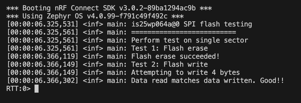
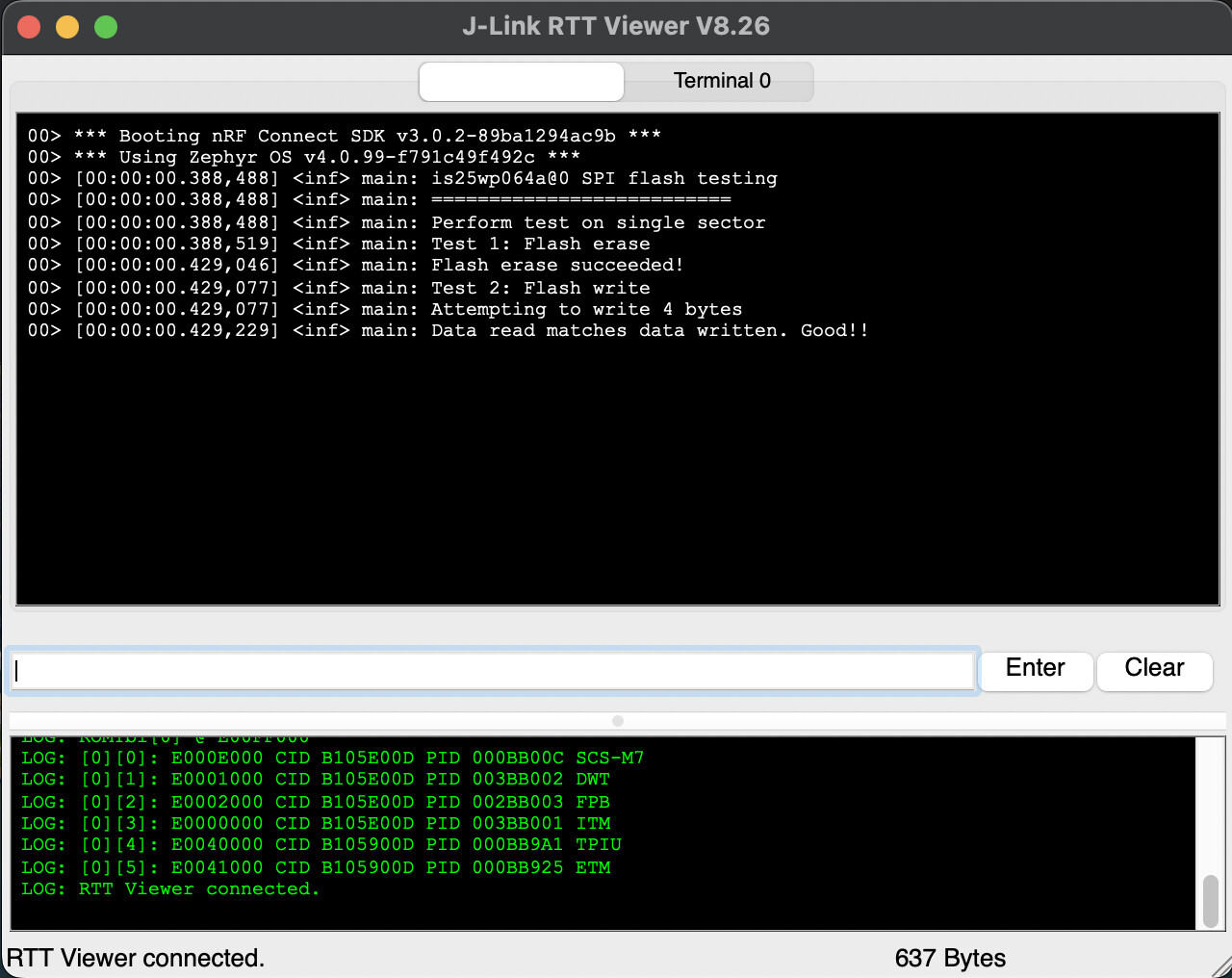
*** Booting nRF Connect SDK v3.0.2-89ba1294ac9b ***
*** Using Zephyr OS v4.0.99-f791c49f492c ***
is25wp064a@0 SPI flash testing
==========================
Perform test on single sector
Test 1: Flash erase
Flash erase succeeded!
Test 2: Flash write
Attempting to write 4 bytes
Data read matches data written. Good!!
After a read of the driver it seemed that the qspi_wait_while_writing was not doing what it’s supposed to do, so I went on to add some LOG_ statements in the nrf_qspi_nor.c driver, removed the polling sleep, and got the confirmation that something is very odd:
- at first the value of the Status Register equals 0x43 (QE=1, WEL=1, WIP=1), which is exactly what we would expect from a flash while it is executing an erase operation
- after less than a millisecond the value of the Status Register returned by the
qspi_rdidfunction is 0x00, which doesn’t make any sense since the erase time is about 70ms…
[00:00:00.261,932] <dbg> qspi_nor: configure_chip: RDSR 40 QE 1 need 1: no-change
*** Booting nRF Connect SDK v3.0.2-89ba1294ac9b ***
*** Using Zephyr OS v4.0.99-f791c49f492c ***
[00:00:00.262,023] <inf> spi_flash: is25wp064a@0 SPI flash testing
[00:00:00.262,054] <inf> spi_flash: ==========================
[00:00:00.262,054] <inf> spi_flash: Perform test on single sector
[00:00:00.262,054] <inf> spi_flash: Test 1: Flash erase
[00:00:00.262,115] <inf> qspi_nor: nrfx_qspi_erase(NRF_QSPI_ERASE_LEN_4KB) ...
[00:00:00.262,115] <inf> qspi_nor: qspi_wait_for_completion ...
[00:00:00.262,145] <inf> qspi_nor: qspi_wait_while_writing ...
[00:00:00.262,207] <inf> qspi_nor: qspi_wait_while_writing: SR=0x43, SPI_NOR_WIP_BIT=1
[00:00:00.262,237] <inf> qspi_nor: qspi_wait_while_writing: SR=0x43, SPI_NOR_WIP_BIT=1
[00:00:00.262,268] <inf> qspi_nor: qspi_wait_while_writing: SR=0x43, SPI_NOR_WIP_BIT=1
[00:00:00.262,298] <inf> qspi_nor: qspi_wait_while_writing: SR=0x43, SPI_NOR_WIP_BIT=1
[00:00:00.262,359] <inf> qspi_nor: qspi_wait_while_writing: SR=0x43, SPI_NOR_WIP_BIT=1
[00:00:00.262,390] <inf> qspi_nor: qspi_wait_while_writing: SR=0x43, SPI_NOR_WIP_BIT=1
[00:00:00.262,420] <inf> qspi_nor: qspi_wait_while_writing: SR=0x43, SPI_NOR_WIP_BIT=1
[00:00:00.262,451] <inf> qspi_nor: qspi_wait_while_writing: SR=0x00, SPI_NOR_WIP_BIT=0
[00:00:00.262,451] <inf> qspi_nor: qspi_wait_while_writing done
[00:00:00.262,542] <inf> spi_flash: Flash erase failed at offset 0xff000 got 0x88888888
Unfortunately I’m running out of ideas on what causes this behaviour… The only thing I’ve seen is that there could be pull-ups on the QSPI_DIO2 and 3 so that the #WP and #RESET do not change state when not driven, although once the QE bit is set (which is the case) they should be ignored ?
I’m also wondering why the flash mounted on the boards is not advertised in the features ? Is it because it was not working ?
Best regards,
Patrick