
Hi,
I want to connect a button to the RAK5005 base board and I don’t want to damage it - so I’m asking for advice first!
Looking at the data sheet I think that using pins 2 and 4 on J11 would work?
Is so, what pin number would I use in my code?
Anything else I need to be a ware of?
Thanks
Alan
Hi @Alangward
Yes, Pins 2 (IO1) and 4 (VDD) should work. But I would propose to use a 10k Ohm resistor between the button and pin 4 instead of directly connecting it. Just my opinion, I would never connect a GPIO directly to Vdd.
Code that should work:
pinMode(WB_IO1, INPUT_PULLDOWN);


if (digitalRead(WB_IO1) ==HIGH)
{
   Serial.println("Button pushed");
}
else
{
   Serial.println("Button released");
}
Also to add, we recently created a new tutorial featuring a LoRaButton Application in our Knowledge Hub 
Hi,
I’ve connected my button and am having problems getting it to work - so I connected my meter to it to check the voltage and found that it sits at about 10mv, but with an occasional ‘blip’. I assumed that with the use of INPUT_PULLUP the voltage would be about 3.3v until the button was pressed.
I checked the 5005 datasheet and discovered that I01 is also connected to module slot A, where I have a GPS module mounted. I think this is interfering with my use of I01 for the button.
Any ideas?
Thanks
Alan
Update.
I have removed the GPS module and now the button works as expected
Is there a different pin I can use for the button?
Alan
Hi Alan,
Yes, unfortunately the GNSS modules (both RAK19010 and RAK12500) have their 1PPS signal connected to GPIO1 (depending on the slot of course). 1PPS gives every 1 second a trigger impulse that can be used by the MCU.
On the RAK5005-O there are no other GPIO’s exposed on the pin headers.
Hi Bernd
Thanks.
I have shuffled my modules around. The GPs is now on slot C and my buzzer is on slot B. Slot A is now free and the button works.
I’m not sure my colleagues are going to be too pleased to have to rebuild their devices!
Thanks
Alan
I spoke too soon!
I have enhanced the button code for it to cause an interrupt when pressed - the interrupt triggers the main loop into action.
So far so good. It then fails (locks up) on the first call to a GPS function: getGnssFixOk(),
So I guess the GPS (in slot C) is unhappy that I am messing with pin I01?
Alan
Must be something else. GPIO1 is not connected on Slot C:
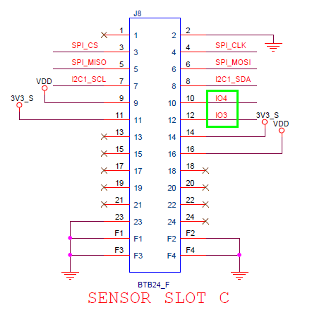
Slot C uses IO3 and IO4
Hi Bernd
Seems the problem was due to a call of delay() in my interrupt routine. I removed that and it now works fine.
Weird. I now need to work out how to implement the logic that used the delay, but outside the interrupt.
Alan
Not weird, an interrupt handler routine should be as short as possible, should never do a Serial.print (might work, but might crash as well) and never do a delay.
just an idea, create a SoftwareTimer instance, start the timer from the interrupt handler. Then after a defined delay, the callback of the SoftwareTimer (which is not an interrupt handler) can do what you need to do.
Thanks.
I spotted the problem as the delay() seemed to be having no effect.
I also had debug printing in there - that’s now gone.
Alan
Hi,
I’m struggling with getting the correct pin numbers set up for my components on the 5005 board.
I have a 12500 GNSS module on slot C. I was not getting any fixes using my current code. I saw that the initialisation was toggling pin WB_I02, which worked when I had it on slot A. Looking at the 5005 data sheet I saw that equivalent connection on slot C was pin WB_I04. I changed the initialisation to use that pin and the module then worked.
However, during my early investigation I had commented out my buzzer code, which uses WB_I02 as the buzzer is now on slot B.
I reinstated the buzzer code after I got the GPS working and the GPS now fails to initialise:
GPS ZOE-M8Q startup(I2C)
u-blox GNSS not detected at default I2C address. Please check wiring. Freezing.
I have a button on WB_I01.
Thanks
Alan
You still need WB_IO2 to control the power supply of the GNSS module. So you cannot use WB_IO2 for the buzzer.
Now if you put WB_IO2 on high for the GNSS initialization, the buzzer might get very hot, because he gets a 3.3V instead of a PWM signal. So better to move the buzzer to another slot.
Juggling with only 7 IO’s can be a headache.
So, it appears that I can’t have push button, a buzzer and a GNSS module worming together on a 5005 base board?
If I add a 13003 expansion module can I connect the button to that and get an interrupt?
Thanks
Alan
Difficult.
The only solution I have is
April 8th
Be patient.