The project I’m building uses a RAK11200 on a 19011 dual IO base with 19016 5-24V power supply module. It sits in an enclosure with a pump controller PCB that has 12V DC power supply. I’m taking the 12V to feed the 19016 and also have a 18650 battery hooked up.
I need to monitor both the power supply presence and the battery voltage. If the mains power flickers, the pump controller resets but thanks to the battery the WisBlock does not…however, in most cases of this fault condition we lose serial communications between the two boards. My solution is to monitor the 5V rail on the controller board, and if it fails and comes back to reset the WisBlock and get back to business. I’m also watching the battery voltage in case of an extended power outage, so that we can send alerts to the server and if the battery drops below 3.7 V put the 11200 into deep sleep.
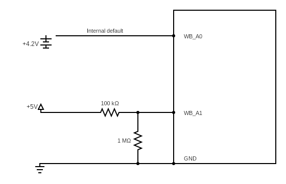
I’ve got the 5V rail connected through a 100K resistor to WB_A1. I’m polling this pin every 500 ms and WB_A0 every 10 seconds to test. With the DC supply gone, I get accurate battery voltage and can watch it slowly discharge from 4.2 down to 3.7V. The problem that has cropped up is that when pin A1 sees 5V, the battery reading jumps to 6.1V. Multimeter tests confirm that right now the battery is actually at 3.85V, and A0 reads 2.185V with the power supply disconnected, 3.525V with it connected.
Is there crosstalk or leakage somewhere that would be showing up on A0?
When you say 5V rail connected through a 100K resistor to WB_A1, does this mean a direct connection without voltage divider? If yes, that could possibly affect the readings. I will suggest to create a simple code for reading both A0 and A1 adc reading. You can exclude the external controller for now and see first if wisblock is performing as expected.
Yes, I forgot to mention that there’s a 1M resistor to ground, creating a voltage divider.
What I will probably do is check for the presence of DC supply and apply a correction factor to the battery reading. It appears to be consistent and pretty linear (although I need to test for this).
Another data point: if I take the battery out completely while DC supply is connected, I still get a 6.1V value and the multimeter reads around 3.3V at A0. So I can’t use the value from A0 at all when I have DC connected.
Stranger still: as both sources are being read, I’m seeing a latch effect on A0. Polling pin A1 drops A0 to 3.26V, but when the battery is polled it jumps to 3.86V. Taking the battery out gives the same pattern but the values decay from peak until the next polling interval (I’m using 5s on the line and 10s on the battery for this test).
I cannot visualize the whole setup. If you can have a simple drawing on connections and also the code you use. I can try it can get more insight. There seems to have A0 and A1 relationship which I don’t understand since they are separate input. It could be something in the setup.
The two functions are both called from void loop() and run with intervals of 500 ms for the power supply and 5 minutes for the battery.
My workaround for now is to only read the battery when the line fails, because that is when it really matters. The boolean pwrSupply is also used to prevent execution of other functions to preserve battery life until it gets to 3.7V, at which time we go into deep sleep.
crosstalk can occur in different analog input systems including audio equipment, data acquistion systems, ans communication systems. it can be caused by factors such as electromagnetic interference capactive coupling or improper layout of circuit traces.
I am doing some validation based on the setup you shared.
I can confirm that there is some effect on the A0 signal when there is a voltage across A1 signal. I can see few LSB difference. We are still investigating what possibly causes this. I will update you asap for any findings we got.
Update: the resistances for my temporary voltage divider were not very good, as this put 4.5V on pin A1. My production values will be 680K for R1 and 1M for R2, giving an effective signal of just under 3V as the top of the range. This should be better for the ADC.
Good findings! If you can have under 3V on the adc pin, that will be great since you will be on the linear section of the EPS32 ADC. As you go 3.3V, the linearity suffers. I suggest you test on that and see if the effects will be acceptable on your application. Else, you can try external ADC which works better than the internal ADC of ESP32.