Custom board, bare stamp module, RAK4630-R+mini base high current consumption

Hello All,

I have an interesting problem that I’m trying to fix. Essentially, I’ve created a custom board that uses the RAK4630-R stamp module, and I’m attempting to get it to sleep properly. I have been able to call the sleep all function that drastically reduces the current, but average consumption still sits near 480-650uA.

Trying the same exact code with just the stamp module connected with 3.3V and GND with fly wires has the same exact consumption pattern, with an average current of ~650uA as well. ( I was convinced that there was parasitic current in my custom board, so I removed the stamp module entirely, turns out current is the same)

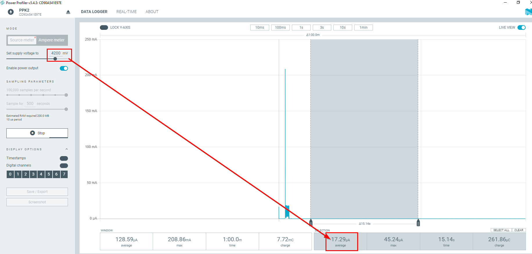
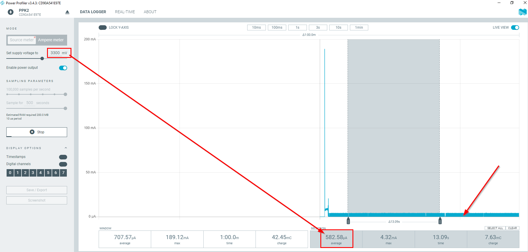
Trying the same code again with the RAK4631-R + a mini base board, powering with 3.3V via the battery terminal with my PK2 shows a much more reasonable average consumption of 62uA. I have confirmed that the sketch starts up and stabilizes ok by the presence of advertisement spikes at the beginning of each run, that settles out eventually once the sleep function kicks in.

base board current:

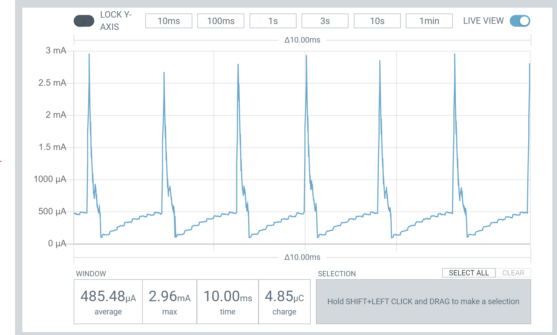
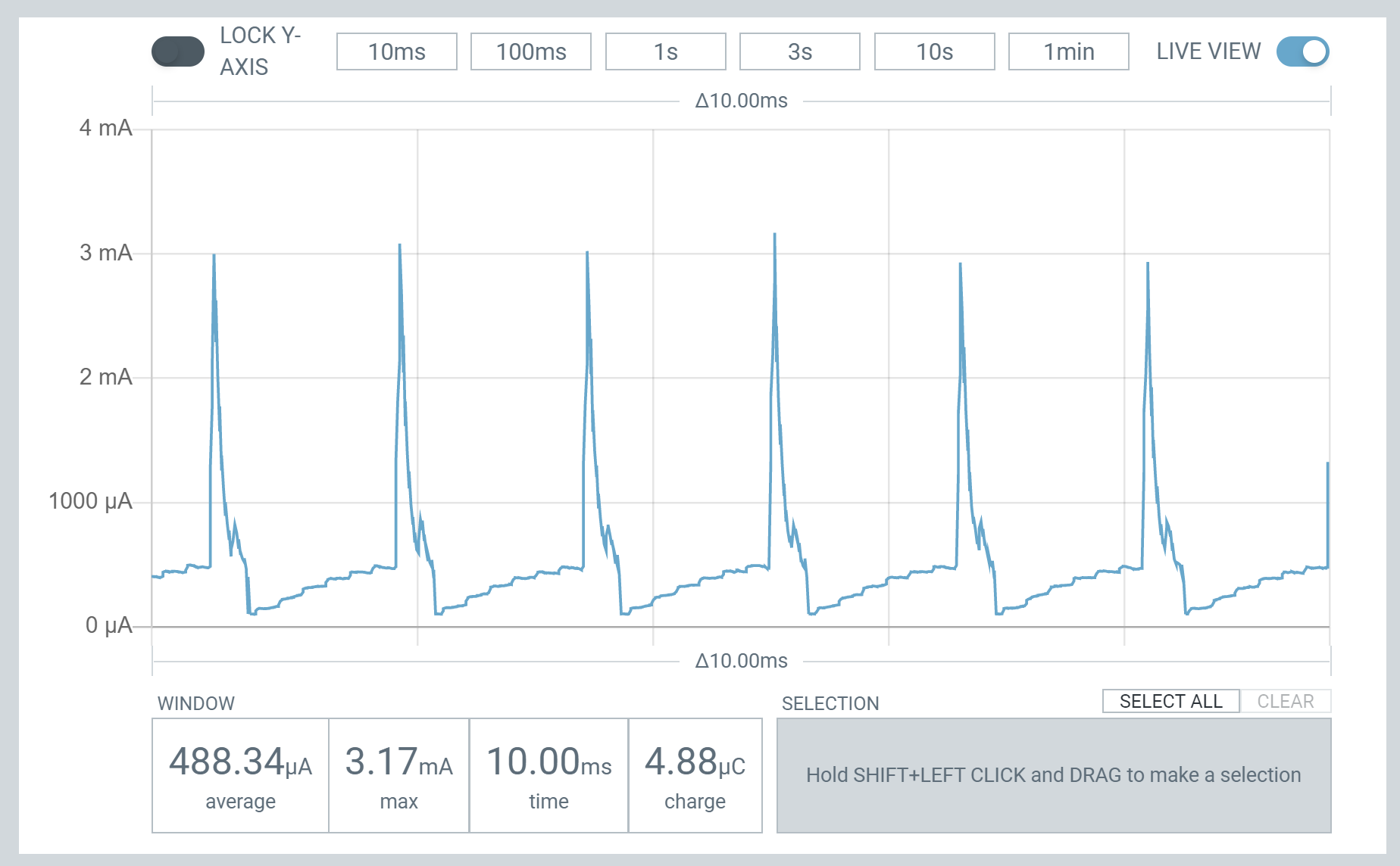
The main difference between 650uA avg cases and that of the mini base board is that the base board doesn’t spike up to 3mA periodically like the other cases do. I believe this is the cause of the extra power consumption. My question is: can anyone explain why these spikes are occurring? Am I missing circuitry that is causing this behavior?

Here is the code run on all modules:

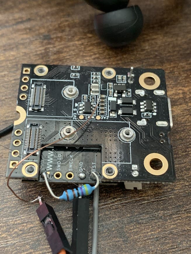
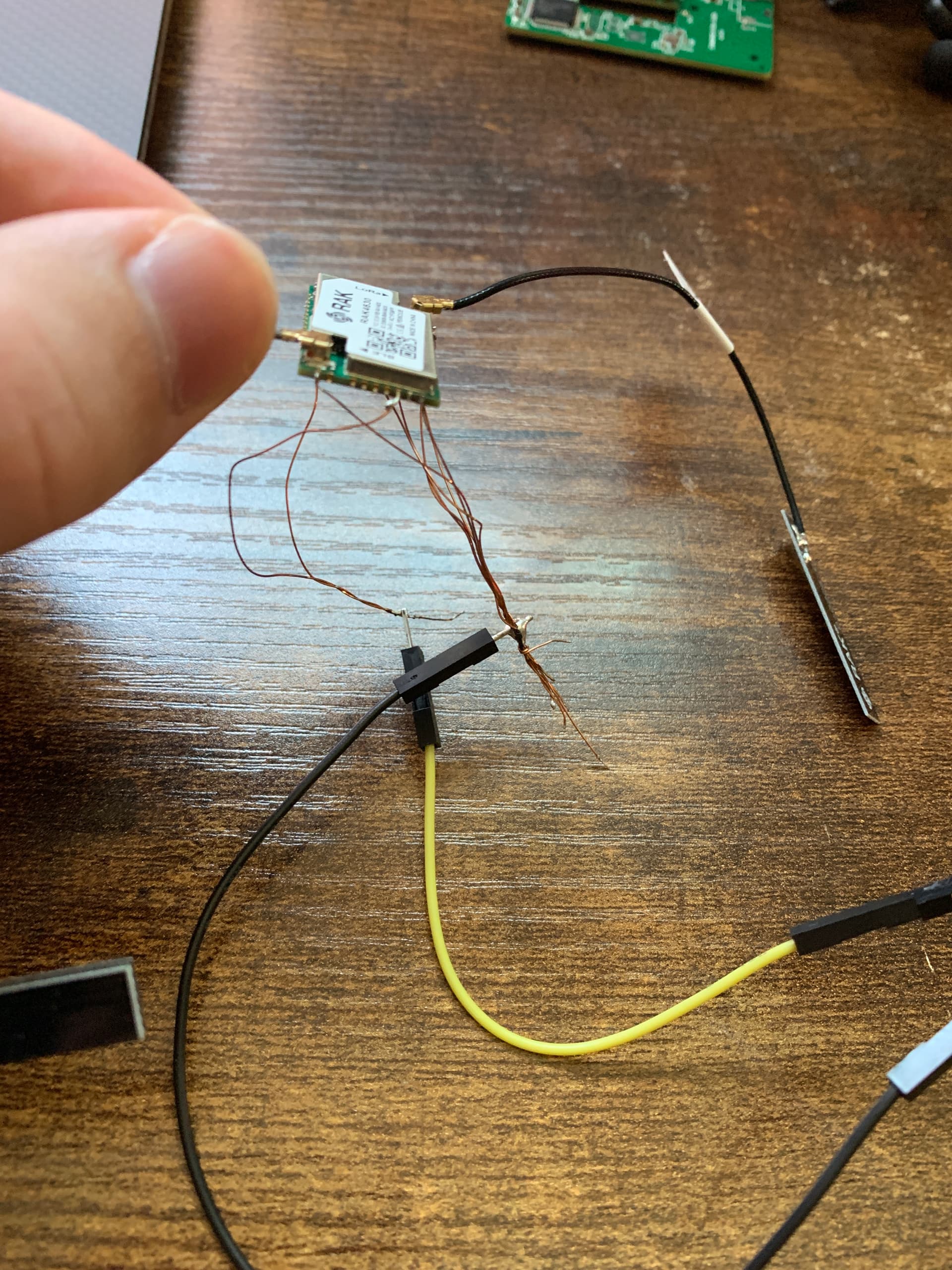
Here is a picture of the flywire module:
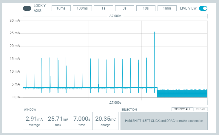

Flywire startup:

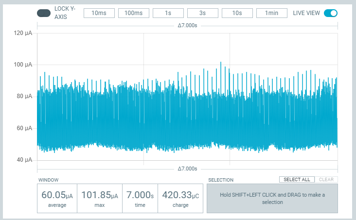
Flywire steady state:

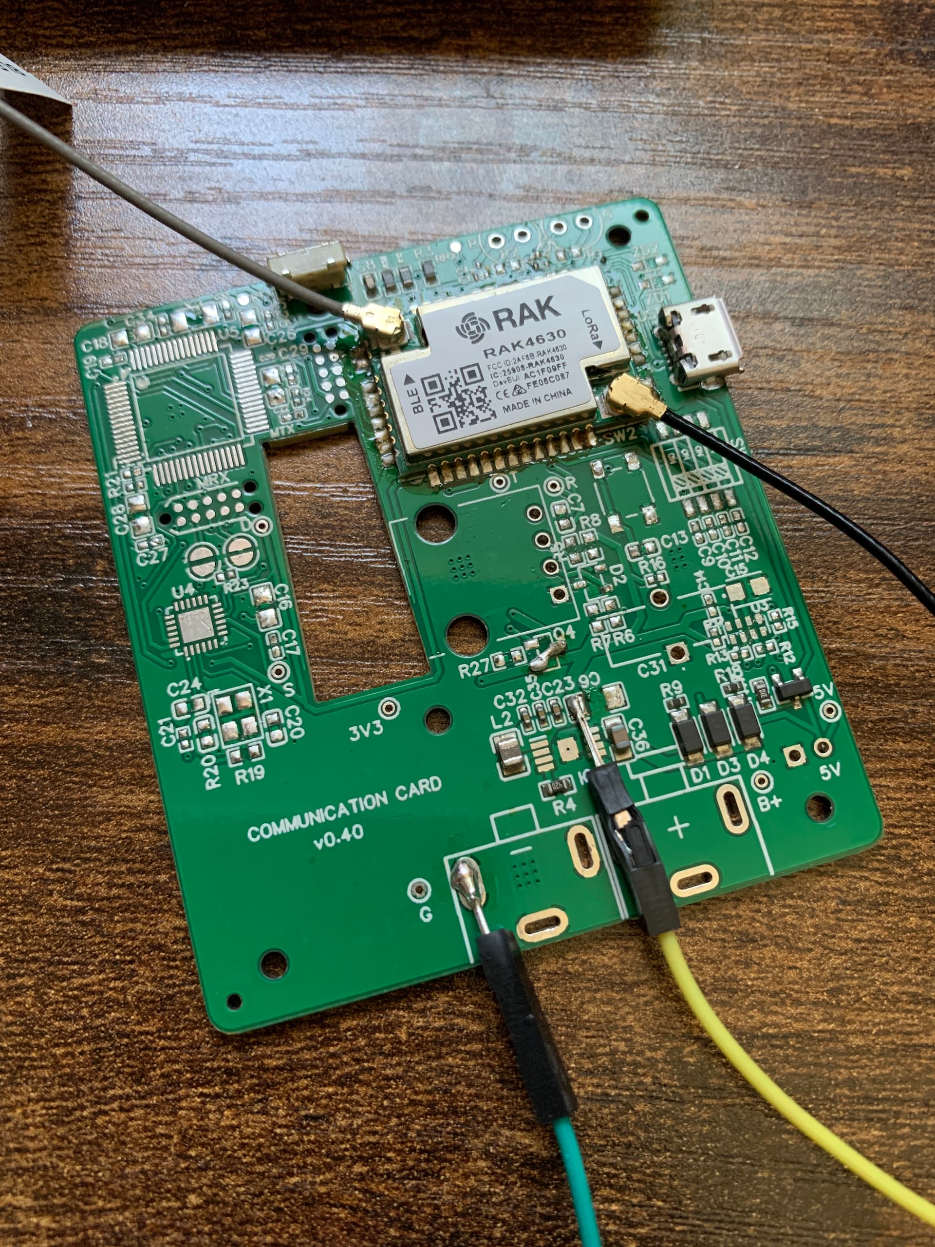
Picture of the custom board, all non-RAK support components have been removed, and is powered directly via 3.3V from my PK2.


Custom board steady state:

Code used for all cases (using the Staging BSP):

void setup() {

}

void loop() {
  api.system.sleep.all(10000);
}

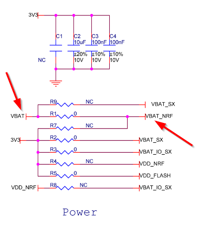
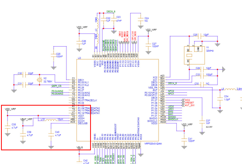
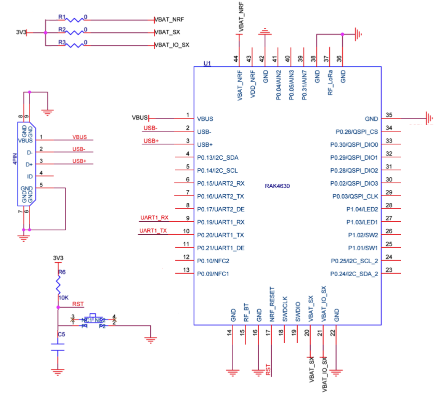
Further FYI, the custom board implements the “bare minimum” circuitry as defined here from the getting started guide:


It’s also worth noting that without the stamp module populated, when powering the board’s 3.3V rail the board only consumes 0.15uA, and that was before I depopulated the unnecessary passives.

The flywire setup should mirror this perfectly, minus the RST circuitry, but that is present on the custom board, and the flywire module starts up OK anyway. If this documentation is correct, seems to me that what I am doing should work. For the record processing and RF activities all happen OK, it’s just sleep that I have not been able to nail down.

@carlrowan @beegee please let me know if tagging the both of you is inappropriate for this forum, I figure you are both the best ones to help this situation, and it’s time sensitive, as this issue is a blocker for our production.

Discussing your problem with the R&D team.

1 Like

@beegee @carlrowan

More information here: I powered a base board with 3.3V via my PK2 in a similar way that I’ve been testing with my custom board, and also got ~650uA current.

It appears that powering the core+base on the 3.3V header on the core board, as well as powering the core+base via the capacitors next to the output of the boost/buck also results in ~600uA average current consumption.

Still not sure why this is though, any more ideas from the team? Can they recreate what I’ve done here to confirm? Doing things this way would be pretty much exactly how I have things on my custom board. I’m even using the same buck/boost IC and capacitor/inductor arrangement, though I didn’t have the IC populated on my boards yet.

Not sure if this helps for your custom board. I can only test with RAK4631 Core module, I do not have a RAk4630 stamp module at hand.

WisBlock Core RAK4631 requires 3.3V and VBat to work, without VBat, it is not working properly => schematic
image

Inside the RAK4631 module, VBat is used to feed the nRF52 DCDC converter => schematic

With Vbat open the DCDC might not work, not sure how to test without a RAK4630 stamp module.

Supplying over the battery connector with 4.2V, I get ~17uA deep sleep:

Supplying over the battery connector with 3.3V only, I get ~582uA. This is not strange because VBat goes into a 3.3V regulator which for sure will not work well with a 3.3V input. I see in this case a lot of noise in the current, which most likely is caused by the too low input voltage.


This noise disappears when I raise the VBat to 3.6V (minimum input for the 3.3V regulator).

Just an idea, can you raise the input voltage of your custom board to 3.6V and test?

@beegee Thanks again for delving into this.

I’ve powered the RAK4631-R + mini base module with 3.3V on the battery terminal and got 60uA previously, I think the extra few dozen uA came from the dc-dc regulator as you indicated, since that makes sense, however I’m not seeing the same ~600uA that way.

Also, I do indeed have VBAT_NRF connected to my 3.3V rail on my custom board, so it should be the same as the 60uA case…still unsure why it is not.

@beegee the only higher voltage I might have is 6.5Vmax from the battery input, otherwise the whole board is 3.3V, so I’m unsure on how to get a higher voltage into this pin without adding an entire other regulator just for VDDH. 6.5V comes from 4x AA batteries on the input.

For all those coming to this thread in the future, the solution appears to be to add a 2nd voltage domain to my board - 3.6V only connected to the VBAT_NRF pin, with 3.3V applied on the other power pins. I’ll likely be adding a 2nd buck to my board just for this purpose, as a work-around.

This is due to the configuration of the RAK4630 circuitry underneath the RF shield, as well as the configuration of the bootloader. Once done, you should get ~14uA average current as expected.

1 Like

This topic was automatically closed 2 days after the last reply. New replies are no longer allowed.