Hi all!
We are unable to setup correctly this configuration :
-
Standalone Installation on a server for Chirpstack with Application server, Network server, and gateway server installed on same machine.
2 Gateway RAK7248 DH4 configured and fully functional
3 Wisblock kit 2 with GPS example.
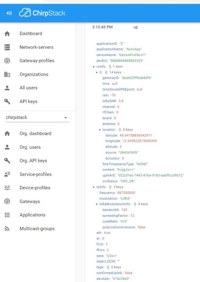
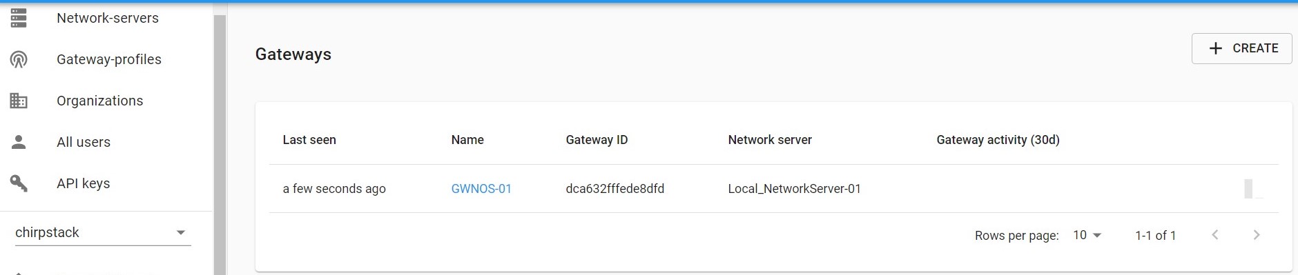
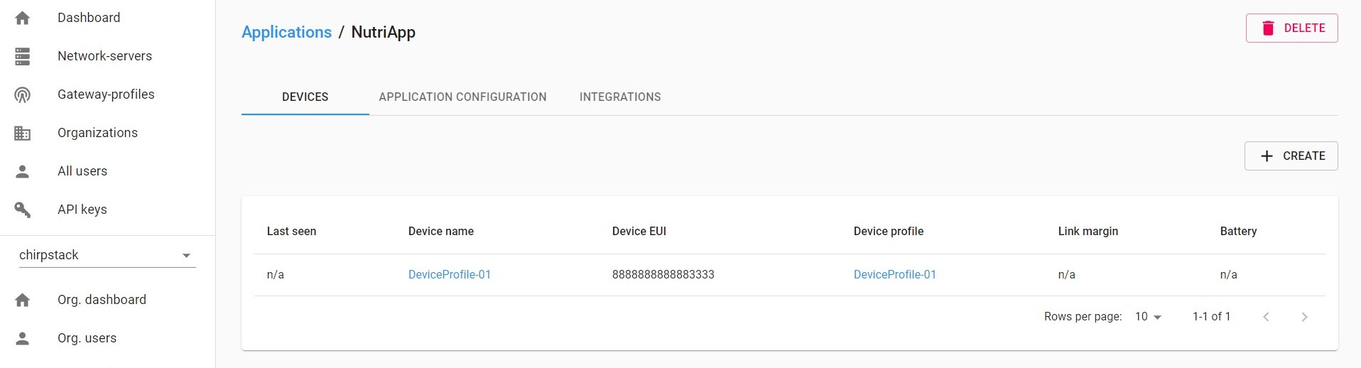
In details, the gateway was able to connect to chirpstack server and also the gateway, the sensor join the network but no data was reiceved.
Here the configuration and some screenshot -
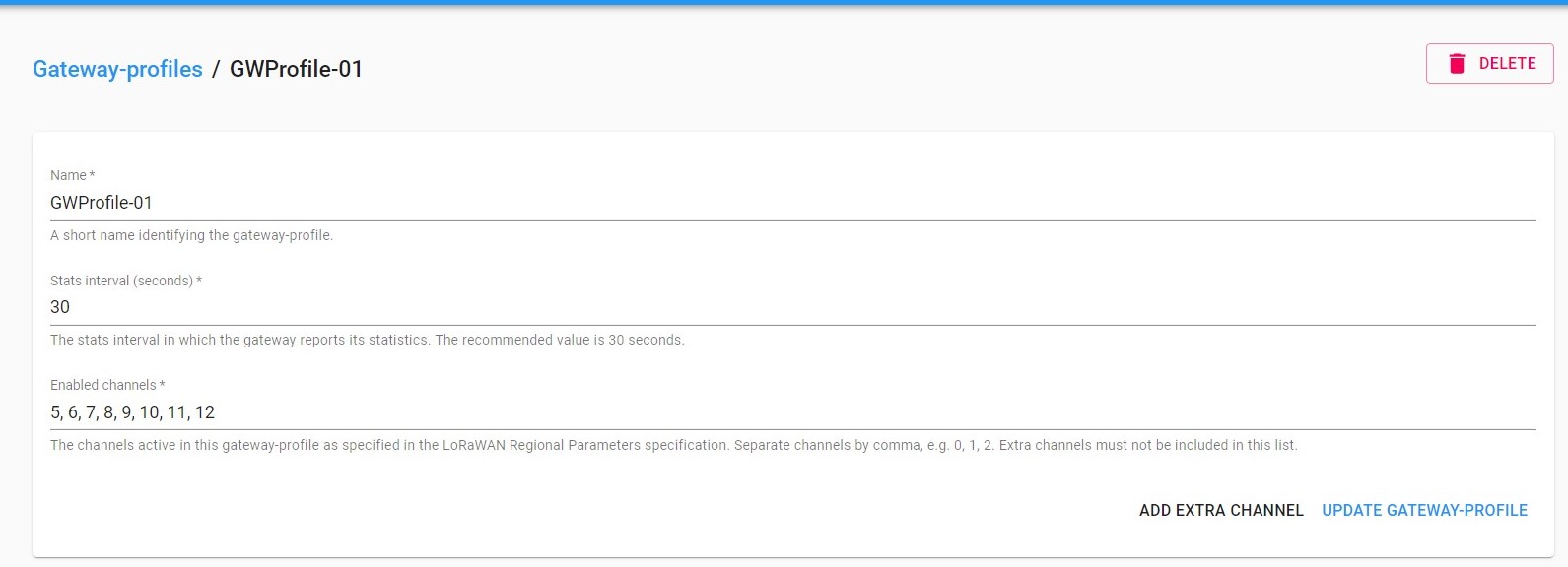
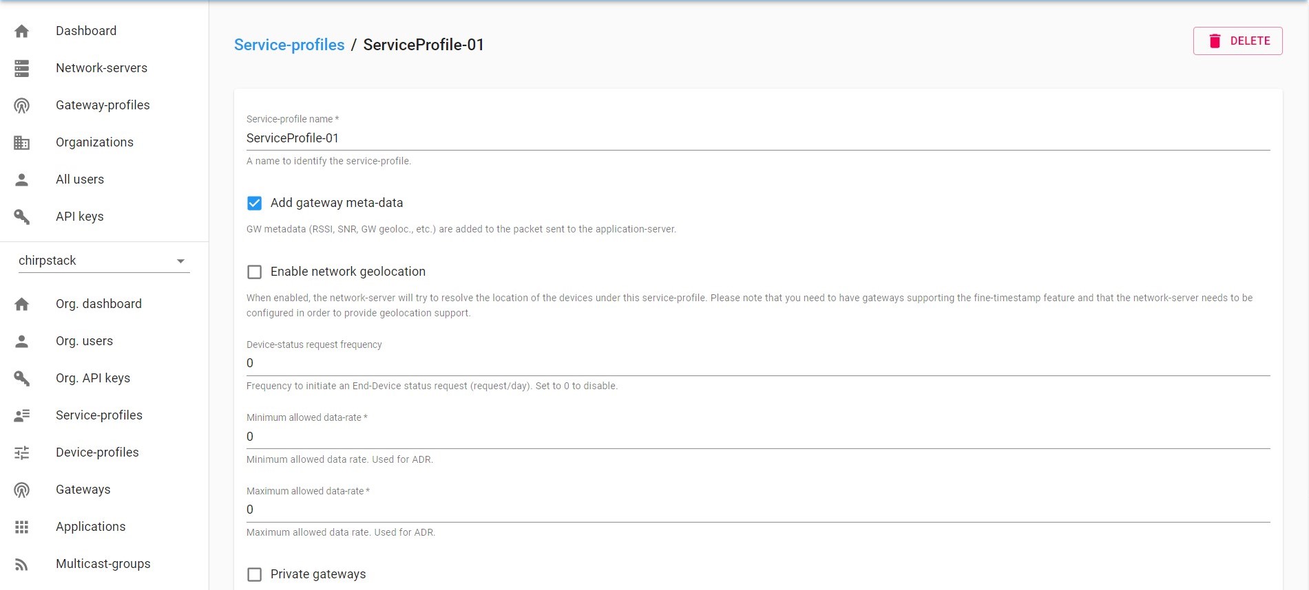
Chirpstack configuration
1.1 chirpstack-gateway-bridge.toml
# This configuration provides a Semtech UDP packet-forwarder backend and
# integrates with a MQTT broker. Many options and defaults have been omitted
# for simplicity.
#
# See https://www.chirpstack.io/gateway-bridge/install/config/ for a full
# configuration example and documentation.


# Gateway backend configuration.
[backend]
# Backend type.
type="semtech_udp"

  # Semtech UDP packet-forwarder backend.
  [backend.semtech_udp]

  # ip:port to bind the UDP listener to
  #
  # Example: 0.0.0.0:1700 to listen on port 1700 for all network interfaces.
  # This is the listener to which the packet-forwarder forwards its data
  # so make sure the 'serv_port_up' and 'serv_port_down' from your
  # packet-forwarder matches this port.
  udp_bind = "0.0.0.0:1700"


# Integration configuration.
[integration]
# Payload marshaler.
#
# This defines how the MQTT payloads are encoded. Valid options are:
# * protobuf:  Protobuf encoding
# * json:      JSON encoding (easier for debugging, but less compact than 'protobuf')
marshaler="protobuf"

  # MQTT integration configuration.
  [integration.mqtt]
  # Event topic template.
  event_topic_template="gateway/{{ .GatewayID }}/event/{{ .EventType }}"

  # Command topic template.
  command_topic_template="gateway/{{ .GatewayID }}/command/#"

  # MQTT authentication.
  [integration.mqtt.auth]
  # Type defines the MQTT authentication type to use.
  #
  # Set this to the name of one of the sections below.
  type="generic"

    # Generic MQTT authentication.
    [integration.mqtt.auth.generic]
    # MQTT server (e.g. scheme://host:port where scheme is tcp, ssl or ws)
    server="tcp://127.0.0.1:1883"

    # Connect with the given username (optional)
    username=""

    # Connect with the given password (optional)
    password=""
1.2 chirpstack-network-server.toml
[general]
log_level=4

[postgresql]
dsn="postgres://chirpstack_ns:xxxxxxxx@localhost/chirpstack_ns?sslmode=disable"

[network_server]
net_id="000000"

  [network_server.band]
  name="EU_863_870"

  [[network_server.network_settings.extra_channels]]
  frequency=867100000
  min_dr=0
  max_dr=5

  [[network_server.network_settings.extra_channels]]
  frequency=867300000
  min_dr=0
  max_dr=5

  [[network_server.network_settings.extra_channels]]
  frequency=867500000
  min_dr=0
  max_dr=5

  [[network_server.network_settings.extra_channels]]
  frequency=867700000
  min_dr=0
  max_dr=5

  [[network_server.network_settings.extra_channels]]
  frequency=867900000
  min_dr=0
  max_dr=5


- Wisblock 2 configuration:
gateway-version
Raspberry Pi 4 Model B Rev 1.4, OS “10 (buster)”, 5.4.79-v7l+.
RAKWireless gateway RAK7248 no LTE version 4.2.7R install from firmware.
Gateway ID: DCA632FFFEDE8DFD.
Packet-forwarder configuration
{
“SX130x_conf”: {
“com_type”: “SPI”,
“com_path”: “/dev/spidev0.0”,
“lorawan_public”: true,
“clksrc”: 0,
“antenna_gain”: 0, /* antenna gain, in dBi /
“full_duplex”: false,
“fine_timestamp”: {
“enable”: false,
“mode”: “all_sf” / high_capacity or all_sf */
},
“radio_0”: {
“enable”: true,
“type”: “SX1250”,
“freq”: 867500000,
“rssi_offset”: -215.4,
“rssi_tcomp”: {“coeff_a”: 0, “coeff_b”: 0, “coeff_c”: 20.41, “coeff_d”: 2162.56, “coeff_e”: 0},
“tx_enable”: true,
“tx_freq_min”: 863000000,
“tx_freq_max”: 870000000,
“tx_gain_lut”:[
{“rf_power”: 12, “pa_gain”: 1, “pwr_idx”: 4},
{“rf_power”: 13, “pa_gain”: 1, “pwr_idx”: 5},
{“rf_power”: 14, “pa_gain”: 1, “pwr_idx”: 6},
{“rf_power”: 15, “pa_gain”: 1, “pwr_idx”: 7},
{“rf_power”: 16, “pa_gain”: 1, “pwr_idx”: 8},
{“rf_power”: 17, “pa_gain”: 1, “pwr_idx”: 9},
{“rf_power”: 18, “pa_gain”: 1, “pwr_idx”: 10},
{“rf_power”: 19, “pa_gain”: 1, “pwr_idx”: 11},
{“rf_power”: 20, “pa_gain”: 1, “pwr_idx”: 12},
{“rf_power”: 21, “pa_gain”: 1, “pwr_idx”: 13},
{“rf_power”: 22, “pa_gain”: 1, “pwr_idx”: 14},
{“rf_power”: 23, “pa_gain”: 1, “pwr_idx”: 16},
{“rf_power”: 24, “pa_gain”: 1, “pwr_idx”: 17},
{“rf_power”: 25, “pa_gain”: 1, “pwr_idx”: 18},
{“rf_power”: 26, “pa_gain”: 1, “pwr_idx”: 19},
{“rf_power”: 27, “pa_gain”: 1, “pwr_idx”: 22}
]
},
“radio_1”: {
“enable”: true,
“type”: “SX1250”,
“freq”: 868500000,
“rssi_offset”: -215.4,
“rssi_tcomp”: {“coeff_a”: 0, “coeff_b”: 0, “coeff_c”: 20.41, “coeff_d”: 2162.56, “coeff_e”: 0},
“tx_enable”: false
},
“chan_multiSF_All”: {“spreading_factor_enable”: [ 5, 6, 7, 8, 9, 10, 11, 12 ]},
“chan_multiSF_0”: {“enable”: true, “radio”: 1, “if”: -400000},
“chan_multiSF_1”: {“enable”: true, “radio”: 1, “if”: -200000},
“chan_multiSF_2”: {“enable”: true, “radio”: 1, “if”: 0},
“chan_multiSF_3”: {“enable”: true, “radio”: 0, “if”: -400000},
“chan_multiSF_4”: {“enable”: true, “radio”: 0, “if”: -200000},
“chan_multiSF_5”: {“enable”: true, “radio”: 0, “if”: 0},
“chan_multiSF_6”: {“enable”: true, “radio”: 0, “if”: 200000},
“chan_multiSF_7”: {“enable”: true, “radio”: 0, “if”: 400000},
“chan_Lora_std”: {“enable”: true, “radio”: 1, “if”: -200000, “bandwidth”: 250000, “spread_factor”: 7,
“implicit_hdr”: false, “implicit_payload_length”: 17, “implicit_crc_en”: false, “implicit_coderate”: 1},
“chan_FSK”: {“enable”: true, “radio”: 1, “if”: 300000, “bandwidth”: 125000, “datarate”: 50000}
},"gateway_conf": { "gateway_ID": "AA555A0000000000", /* change with default server address/ports */ "server_address": "51.89.xx.xx", "serv_port_up": 1700, "serv_port_down": 1700, /* adjust the following parameters for your network */ "keepalive_interval": 10, "stat_interval": 30, "push_timeout_ms": 100, /* forward only valid packets */ "forward_crc_valid": true, "forward_crc_error": false, "forward_crc_disabled": false, /* GPS configuration */ "gps_tty_path": "/dev/ttyAMA0", /* GPS reference coordinates */ "ref_latitude": 0.0, "ref_longitude": 0.0, "ref_altitude": 0, /* Beaconing parameters */ "beacon_period": 0, /* disable class B beacon, set to 128 enable beacon */ "beacon_freq_hz": 869525000, "beacon_freq_nb": 1, "beacon_freq_step": 0, "beacon_datarate": 9, "beacon_bw_hz": 125000, "beacon_power": 27 }, "debug_conf": { "ref_payload":[ {"id": "0xCAFE1234"}, {"id": "0xCAFE2345"} ], "log_file": "loragw_hal.log" }}
- Wisblock 2 sketch
#include <Arduino.h>
#include <LoRaWan-RAK4630.h>
#include <SPI.h>
#include “SparkFunLIS3DH.h”
#include “Wire.h”
#include <SoftwareSerial.h>SoftwareSerial Serial3(15, 16); //GPS_UART_RX,GPS_UART_TX
LIS3DH SensorTwo( I2C_MODE, 0x18 );// RAK4630 supply two LED
#ifndef LED_BUILTIN
#define LED_BUILTIN 35
#endif#ifndef LED_BUILTIN2
#define LED_BUILTIN2 36
#endifbool doOTAA = true;
#define SCHED_MAX_EVENT_DATA_SIZE APP_TIMER_SCHED_EVENT_DATA_SIZE /< Maximum size of scheduler events. */
#define SCHED_QUEUE_SIZE 60 /< Maximum number of events in the scheduler queue. /
#define LORAWAN_DATERATE DR_0 /LoRaMac datarates definition, from DR_0 to DR_5/
#define LORAWAN_TX_POWER TX_POWER_5 /LoRaMac tx power definition, from TX_POWER_0 to TX_POWER_15/
#define JOINREQ_NBTRIALS 3 /**< Number of trials for the join request. /
DeviceClass_t gCurrentClass = CLASS_A; / class definition/
lmh_confirm gCurrentConfirm = LMH_CONFIRMED_MSG; /* confirm/unconfirm packet definition*/
uint8_t gAppPort = LORAWAN_APP_PORT; /* data port*//**@brief Structure containing LoRaWan parameters, needed for lmh_init()
*/
static lmh_param_t lora_param_init = {LORAWAN_ADR_ON , LORAWAN_DATERATE, LORAWAN_PUBLIC_NETWORK, JOINREQ_NBTRIALS, LORAWAN_TX_POWER, LORAWAN_DUTYCYCLE_OFF};// Foward declaration
static void lorawan_has_joined_handler(void);
static void lorawan_rx_handler(lmh_app_data_t *app_data);
static void lorawan_confirm_class_handler(DeviceClass_t Class);
static void send_lora_frame(void);/**@brief Structure containing LoRaWan callback functions, needed for lmh_init()
*/
static lmh_callback_t lora_callbacks = {BoardGetBatteryLevel, BoardGetUniqueId, BoardGetRandomSeed,
lorawan_rx_handler, lorawan_has_joined_handler, lorawan_confirm_class_handler};//OTAA keys
uint8_t nodeDeviceEUI[8] = {0x88, 0x88, 0x88, 0x88, 0x88, 0x88, 0x33, 0x33};
uint8_t nodeAppEUI[8] = {0xB8, 0x27, 0xEB, 0xFF, 0xFE, 0x39, 0x00, 0x00};
uint8_t nodeAppKey[16] = {0x88, 0x88, 0x88, 0x88, 0x88, 0x88, 0x88, 0x88,0x88, 0x88, 0x88, 0x88, 0x88, 0x88, 0x33, 0x33};// Private defination
#define LORAWAN_APP_DATA_BUFF_SIZE 64 /< buffer size of the data to be transmitted. */
#define LORAWAN_APP_INTERVAL 10000 /< Defines for user timer, the application data transmission interval. 10s, value in [ms]. */
static uint8_t m_lora_app_data_buffer[LORAWAN_APP_DATA_BUFF_SIZE]; //< Lora user application data buffer.
static lmh_app_data_t m_lora_app_data = {m_lora_app_data_buffer, 0, 0, 0, 0}; //< Lora user application data structure.TimerEvent_t appTimer;
static uint32_t timers_init(void);
static uint32_t count = 0;
static uint32_t count_fail = 0;void setup()
{
pinMode(LED_BUILTIN, OUTPUT);
digitalWrite(LED_BUILTIN, LOW);// Initialize LoRa chip.
lora_rak4630_init();// Initialize Serial for debug output
Serial.begin(115200);
while(!Serial){delay(10);}
Serial.println(“=====================================”);
Serial.println(“Welcome to RAK4630 LoRaWan!!!”);
Serial.println(“Type: OTAA”);#if defined(REGION_AS923)
Serial.println(“Region: AS923”);
#elif defined(REGION_AU915)
Serial.println(“Region: AU915”);
#elif defined(REGION_CN470)
Serial.println(“Region: CN470”);
#elif defined(REGION_CN779)
Serial.println(“Region: CN779”);
#elif defined(REGION_EU433)
Serial.println(“Region: EU433”);
#elif defined(REGION_IN865)
Serial.println(“Region: IN865”);
#elif defined(REGION_EU868)
Serial.println(“Region: EU868”);
#elif defined(REGION_KR920)
Serial.println(“Region: KR920”);
#elif defined(REGION_US915)
Serial.println(“Region: US915”);
#elif defined(REGION_US915_HYBRID)
Serial.println(“Region: US915_HYBRID”);
#else
Serial.println(“Please define a region in the compiler options.”);
#endif
Serial.println(“=====================================”);//lis3dh init
if( SensorTwo.begin() != 0 )
{
Serial.println(“Problem starting the sensor at 0x18.”);
}
else
{
Serial.println(“Sensor at 0x18 started.”);
}
//gps init
pinMode(17, OUTPUT);
digitalWrite(17, HIGH);
pinMode(34,OUTPUT);
digitalWrite(34,0);
delay(1000);
digitalWrite(34,1);
delay(1000);
Serial3.begin(9600);
while(!Serial3);
Serial.println(“gps uart init ok!”);//creat a user timer to send data to server period
uint32_t err_code;err_code = timers_init();
if (err_code != 0)
{
Serial.printf(“timers_init failed - %d\n”, err_code);
}// Setup the EUIs and Keys
lmh_setDevEui(nodeDeviceEUI);
lmh_setAppEui(nodeAppEUI);
lmh_setAppKey(nodeAppKey);// Initialize LoRaWan
err_code = lmh_init(&lora_callbacks, lora_param_init,doOTAA);
if (err_code != 0)
{
Serial.printf(“lmh_init failed - %d\n”, err_code);
}// Start Join procedure
lmh_join();
}void loop()
{
// Handle Radio events
Radio.IrqProcess();
}/**@brief LoRa function for handling HasJoined event.
*/
void lorawan_has_joined_handler(void)
{
Serial.println(“OTAA Mode, Network Joined!”);lmh_error_status ret = lmh_class_request(gCurrentClass);
if(ret == LMH_SUCCESS)
{
delay(1000);
TimerSetValue(&appTimer, LORAWAN_APP_INTERVAL);
TimerStart(&appTimer);
}
}/**@brief Function for handling LoRaWan received data from Gateway
*
- @param[in] app_data Pointer to rx data
*/
void lorawan_rx_handler(lmh_app_data_t *app_data)
{
Serial.printf(“LoRa Packet received on port %d, size:%d, rssi:%d, snr:%d, data:%s\n”,
app_data->port, app_data->buffsize, app_data->rssi, app_data->snr, app_data->buffer);}
void lorawan_confirm_class_handler(DeviceClass_t Class)
{
Serial.printf(“switch to class %c done\n”, “ABC”[Class]);
// Informs the server that switch has occurred ASAP
m_lora_app_data.buffsize = 0;
m_lora_app_data.port = gAppPort;
lmh_send(&m_lora_app_data, gCurrentConfirm);
}void send_lora_frame(void)
{
if (lmh_join_status_get() != LMH_SET)
{
//Not joined, try again later
return;
}lmh_error_status error = lmh_send(&m_lora_app_data, gCurrentConfirm); if (error == LMH_SUCCESS) { count++; Serial.printf("lmh_send ok count %d\n", count); } else { count_fail++; Serial.printf("lmh_send fail count %d\n", count_fail); } TimerSetValue(&appTimer, LORAWAN_APP_INTERVAL); TimerStart(&appTimer);}
String comdata = “”;
/* return 0 ok, 1 fail*/
/$GPRMC,080655.00,A,4546.40891,N,12639.65641,E,1.045,328.42,170809,A60*/
int parse_gps()
{
if(comdata.indexOf(“,V,”)!= -1)
return 1;return 0;
}
/**@brief Function for handling a LoRa tx timer timeout event.
*/
String data=“”;
void tx_lora_periodic_handler(void)
{
uint32_t i = 0;
uint32_t j = 0;
uint32_t k = 0;
int res = 1;
float x = 0;
float y = 0;
float z = 0;
float z1 = 0;
Serial.println(“check acc!”);
x = SensorTwo.readFloatAccelX()*1000;
y = SensorTwo.readFloatAccelY()*1000;
z = SensorTwo.readFloatAccelZ()*1000;
data = “X = “+String(x)+“mg”+” Y = “+String(y)+“mg”+” Z =”+String(z)+“mg”;
Serial.println(data);
if( abs(x-z) < 400)
{
while (Serial3.available() > 0){
// get the byte data from the GPS
comdata += char(Serial3.read());
delay(2);
if(comdata.indexOf(“GPRMC”)!= -1 && comdata.indexOf(“GPVTG”)!= -1)
{
break;
}
}Serial.println(comdata); res = parse_gps(); if(res == 1) { TimerSetValue(&appTimer, LORAWAN_APP_INTERVAL); TimerStart(&appTimer); return; } delay(1000); j = comdata.indexOf(",A,"); j = j+3; if(comdata.indexOf(",E,") != -1) { k = comdata.indexOf(",E,"); k = k+1; } else { k = comdata.indexOf(",W,"); k = k+1; } memset(m_lora_app_data.buffer, 0, LORAWAN_APP_DATA_BUFF_SIZE); m_lora_app_data.port = gAppPort; m_lora_app_data.buffer[i++] = 0x09; m_lora_app_data.buffer[i++] = ','; while(j!=k+1) { m_lora_app_data.buffer[i++] = comdata[j]; j++; } m_lora_app_data.buffsize = i; comdata = ""; send_lora_frame();}
else
{
TimerSetValue(&appTimer, LORAWAN_APP_INTERVAL);
TimerStart(&appTimer);
}
}/**@brief Function for the Timer initialization.
*
- @details Initializes the timer module. This creates and starts application timers.
*/
uint32_t timers_init(void)
{
TimerInit(&appTimer, tx_lora_periodic_handler);
return 0;
}
Codelink : https://github.com/RAKWireless/WisBlock/tree/master/examples/RAK4630/solutions/GPS_Tracker
The code was copied from tutorial (not the latest deployed)
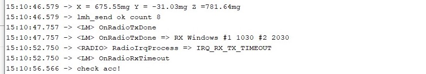
Serial output
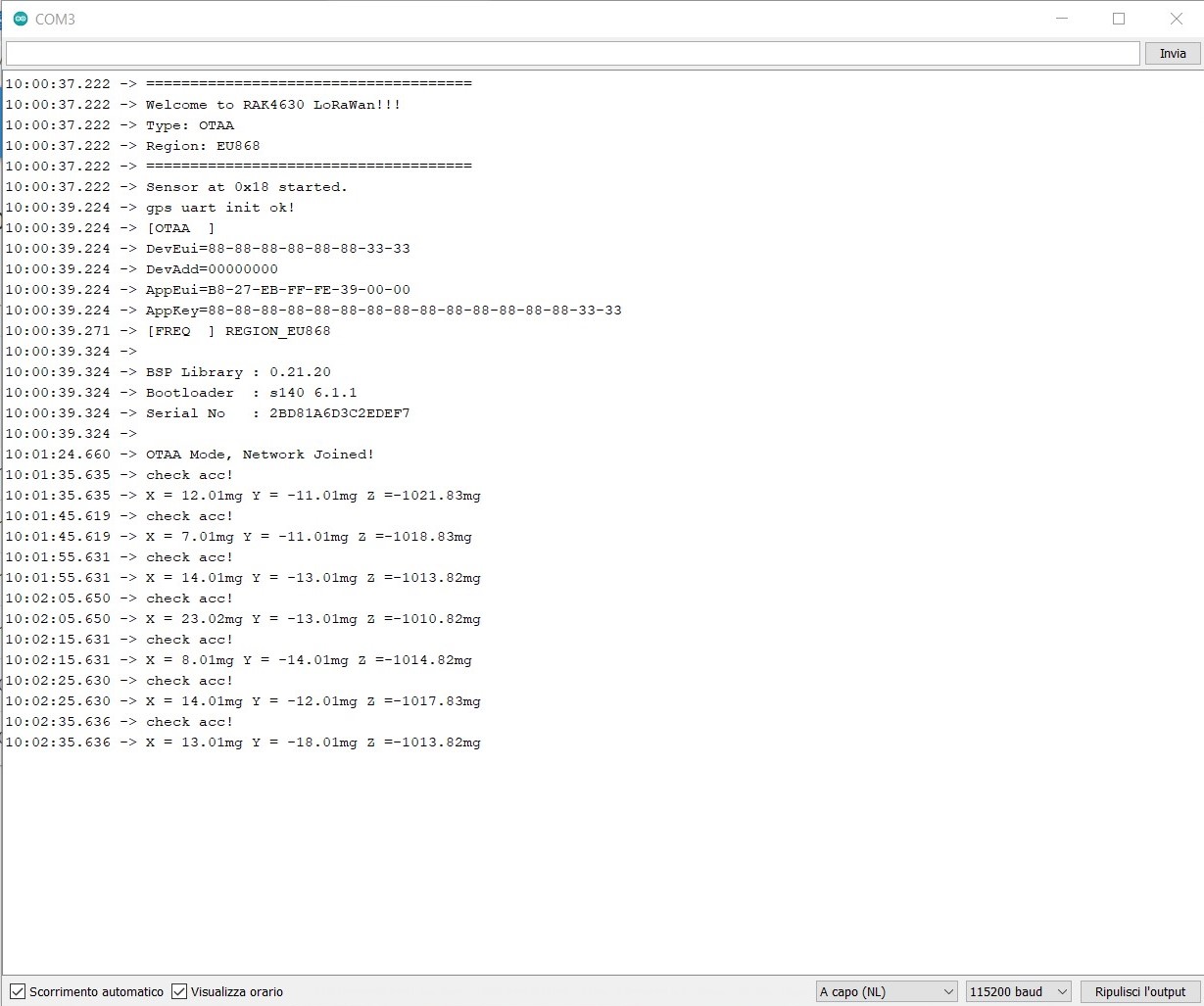
Can someone help me? I’m unable to see where is the misconfiguration! I have spent a week without success.
Thanks!