I’ve seen a few example on dowlinking from the TTN network to a LoRa device. But I can’t seem to find any infomation on how to Downlink from the Helium Console (cloud) to the Rak Dev Kit (RAK4630).
I have it connected and Uplinking Data. But what pins could I even output a signal to?
Also I just so happened to pick up an IO Adapter for the kit too (RAK13002).
Would love to get this figured out so I could share how I did it.
Hi @Ladd12
I know only how to do manual downlink from Helium to the device. I do not know if Helium supports any automated downloads (from MQTT maybe?). You need to check the Helium Console documentation how to do it.
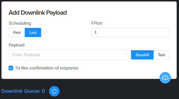
For manual downlink, open Helium Console, open yur device and then click on the blue downlink button on the right side:
Then replace the function lorawan_rx_handler() in the example with this one:
void lorawan_rx_handler(lmh_app_data_t *app_data)
{
  Serial.printf("LoRa Packet received on port %d, size:%d, rssi:%d, snr:%d\n",
                app_data->port, app_data->buffsize, app_data->rssi, app_data->snr);

  for (int idx = 0; idx < app_data->buffsize; idx++)
  {
    Serial.printf("0x%0X", app_data->buffer[idx]);
  }
  Serial.println();

  if (app_data->buffer[0] == 'G')
  {
    // Handle Green LED
    if (app_data->buffer[1] == '0')
    {
      // Switch LED off
      digitalWrite(LED_GREEN, LOW);
    }
    else
    {
      // Switch LED off
      digitalWrite(LED_GREEN, HIGH);
    }
  }
  if (app_data->buffer[0] == 'B')
  {
    // Handle BLUE LED
    if (app_data->buffer[1] == '0')
    {
      // Switch LED off
      digitalWrite(LED_BLUE, LOW);
    }
    else
    {
      // Switch LED off
      digitalWrite(LED_BLUE, HIGH);
    }
  }
}
You can downlink four commands. To make it easier, I used just a string:
Command
Base64
Function
G0
RzA=
Switch green LED off
G1
RzE=
Switch green LED on
B0
QjA=
Switch blue LED off
B1
QjE=
Switch blue LED on
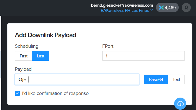
In the Helium Console, go to the Downlink window as shown in my previous post and enter the command there, e.g. Switch Blue LED on:
You’re a Rockstar @beegee. That’s exactly what I needed. It works like a charm. I’ll work on the other aspects and update the thread as I go. This will be a good one for people to use as a future reference.
Not sure what you mean with “check for connectivity”. LoRaWAN “hopes” the gateway is in range and the network server is connected. If the connection is broken, the sent packet just gets lost.
There are a few methods to check if the connection is ok:
send periodically a packet with “Confirmed Mode”, which expects an ACK from the server. If no ACK is received, the packet was not received by the LoRaWAN server
LinkCheck, which is a LoRaWAN Stack command, but the SX1216x-Arduino library does not support it.
Look for LORAWAN_APP_INTERVAL, it is defined as 20000, which means sending a packet every 20 seconds. You can change that to bigger values.
I don’t recommend smaller values, as a packet transmission can take up to 6 seconds, so it is not advisable to user lower values.
Any IO1 to IO6 on the RAK13002 will work unless you use other modules. Then you need to check what IO’s are occupied by other modules.
Be careful with driving a relay directly, the current on the IO pins is limited, it has only 3.3V and you need to add a diode to protect the IO’s from back-current from the coil of the relay.
Best would be to use a transistor to drive the relay and have the IO only control the transistor. Plenty of schematics about this in the internet.