This is a fairly quick question. Do you have to do anything to enable the U.FL connector? I’m getting very bad RSSI and range when using the U.FL connector and am trying to troubleshoot the problem.
When using the SMA connector I’m getting RSSI in the -40 to -50 dB range, when using U.FL I’m in the -105 dB range at around 20 metres.
A special piece of engineering with a expected life of about 5 uses - SparkFun even have a whole blog post on how to unplug things without ripping them apart. This applies to the cable as well.
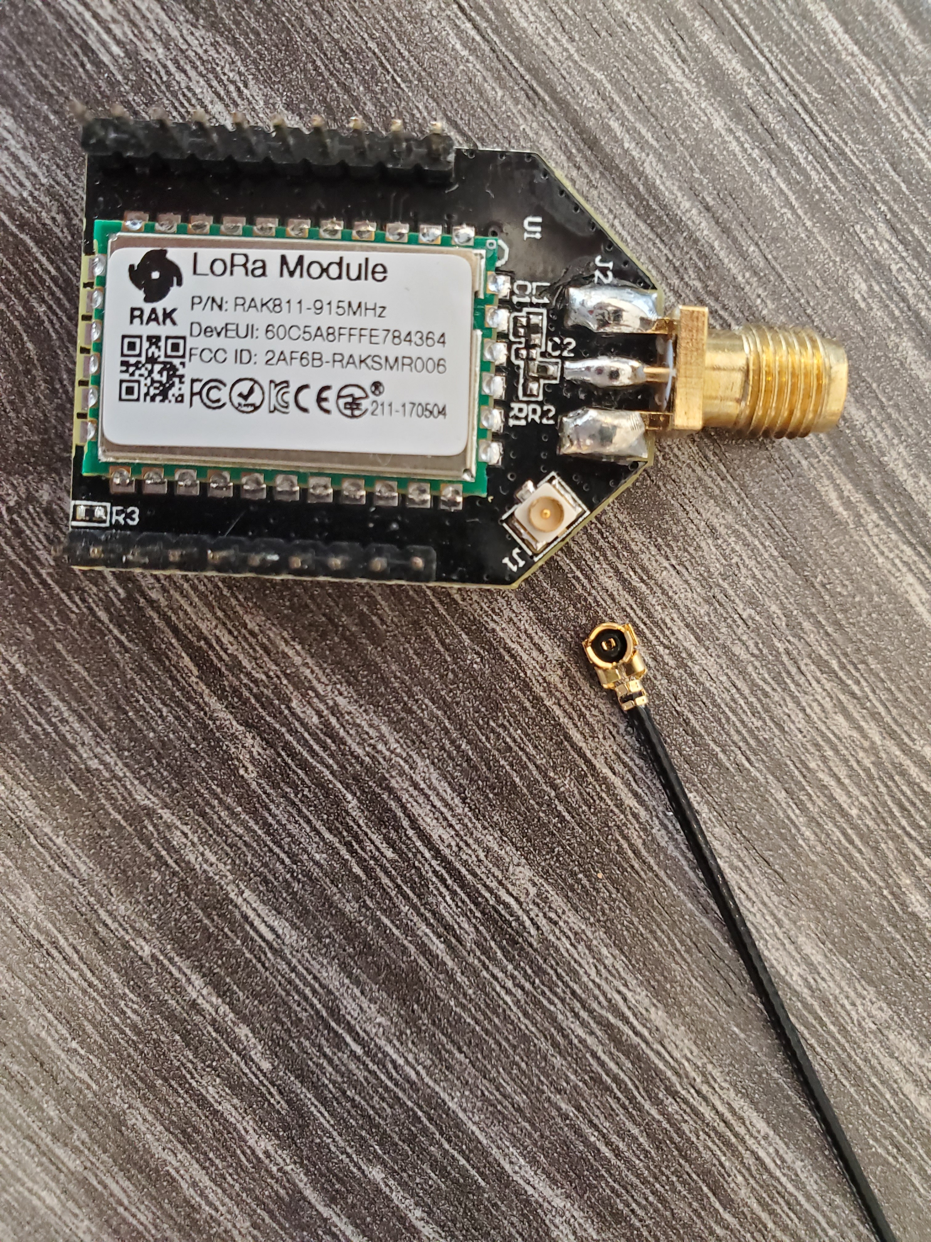
If you are feeling brave, you could lightly touch up the three connectors on the socket on the board, just to make sure they are well connected.
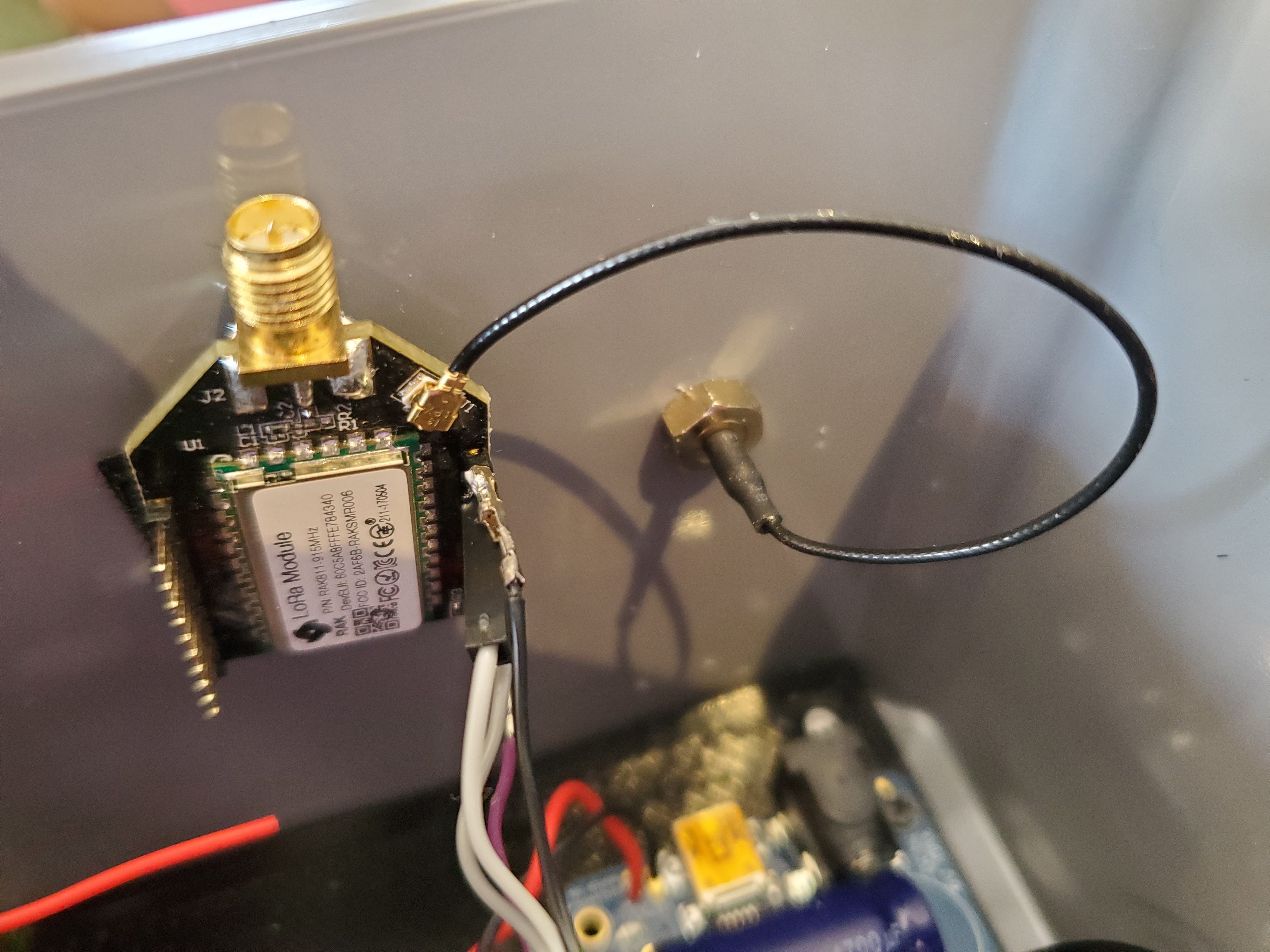
@Nicholas was saying, only use one at a time but from your pictures, you’ve got that.
Just to confirm you do not need to physically do anything to enable the U.FL connector on the breakout board, I should be able to use the SMA connector and U.FL connector out of the box?
Do you have any suggestions as to why the RSSI might be dropping so much? I tried with brand new out of box RAK811 breakout radio and U.FL cable with new antenna. This isn’t common for RSSI to drop so much when using U.FL as opposed to SMA right?
A solid U.Fl connection is fine as long as you don’t plug & unplug a lot.
It may well be you’ve got something in the mix that isn’t up to spec - as a small scale electronics manufacturing house, you’ll not believe the sort of messes we can get in to with substitute parts, different solder pastes, different staff, different oven temps etc etc.
So I have a box locked in a draw of known good parts for testing things when faced with such a situation. But as U.Fl is so delicate, that can be a tricky process.
Ideally you need something else that you know works to plug the cable in to - and look at the results. Then the same with the antenna. Then both together. And, ideally, have another make/brand of cable & antenna, confirm that’s the same. Then try it back on the RAK811 board.
As most of my prototyping is on my very cluttered desk, I only do SMA but I do routinely deploy using the U.Fl so it’s not a general thing.
After phoning in to Rak support crew I was told that I should actually be moving R2 on the schematic 90 degrees to enable U.FL connector. I’m a bit confused about the conflicting advice?
Not surprised - this is news to me - but it is traditional for documentation to trail well behind production
I can see two resistors on the schematic, both 0R, I’ll have to look at a board physically to understand the turning bit - seems removal is likely to be easier with the size of the these SMD parts. Just to keep us confused, the RF out has a filter with two capacitors of value NC and an inductor marked 0R …