I have a working RAK5010 with an external sensor which is doing everything we need it to do except that when the client runs the battery out, the device will no longer charge or turn on when power is applied. If I disconnect my sensor, then apply power, the RAK5010 will turn on so it appears that my sensor is draining power and there isn’t enough to boot.
I have a SGP30 device that is wired as:
J9 Pin 1 (1.8V J-Link ref) → VREF J12 Pin 1 is also the 1.8V for my device.
J9 Pin 4 GND ----> SPG30 Ground
J12 PIN 3 and 4 as the SDA/SCL pins
I’m able to connect to my device, read data, etc. When battery drops and the power turns off, the client is not able to turn device on just by plugging the power cable back in.
Other devices that I have that do not have the external sensor will power back on if the device runs out of power.
So, I’m trying to figure out a better way to connect my SGP30 device and tried to make NRF_I02 an output and set it to LOW so it could be a ground for my device. That didn’t work.
I’d like to keep this simple and user friendly as they do not have access to the power button.
For reference, this the device I’m trying to connect:
Again, it works fine until power forces the device to shut off then I’m not able to turn it back on w/ just applying power unless the SGP30 device is unplugged.
It is a good information that you identified that SGP30 is the specific module causing the problem. Could it be that the module is not operating properly when then battery is low or could be that the I2C bus hangs as well for some reason? Or can it be that the NRF is not able to reinitialized the module when the battery is low?
Since you said that the issue is happening when the battery is drained, can you avoid that scenario? Can you disable the module when you see that the battery nearing drain?
It can also be a good idea to test it with power supply first and identify at what voltage the issue kicks in. Get some serial output for debugging and have a look on the I2C bus too. You might need to implement some proper exit routine before the battery got drained.
My intent is to disable the module when power is below a certain level. What I don’t know is if I need to remove power to the device or if I can just not attempt to initialize the device. I was attempting to use NRF_IO2 as an OUTPUT and make it LOW to be the ground for the SPG30. But in doing so the REF voltage seems to be a bit off and I’m not getting readings from the SPG30. I could throw a MOSFET in the mix to use it as a switch to engage/disengage the SPG30.
But, I think I’ll try your idea first and not even call the INIT function on the SPG30 when power is below a certain level. That may resolve the issue which could be that the NRF is just locking up.
It appears that I’m having an issue when I connect VREF to VDD on some RAK5010 devices. If the battery drains and the device stops working, applying power to the USB buss does NOT start the device back up. Even if I remove my sensor the issue persists. The way I was able to get it to start up when applying power is to unsolder the connection between VDD and VREF. *** UPDATE BELOW ****
Is this possible? Is the device in somehow a locked state?
This does not happen with all my test devices, just some.
My SPG30 device connects to GND, VDD (1.8V), IO3 and IO4. VDD and VREF are connected together.
UPDATE
I ran the test a couple more times and disconnecting VREF is not the solution. The device got into a “locked state” and nothing I did would cause it to boot back up when I applied power via the USB cable.
I even removed the battery, plugged the USB cable in and still nothing. Pressing the PWR button was the only way to start it back up…
Yes, that sounds silly as I type it as PWR would indicate that you have to turn it on, but almost all my other devices, just plugging in the USB cable causes them to start up. Or in most cases, just plugging the battery in causes it to start up.
I’ve tested various boards and some do not start up when power is applied (either battery or USB) and some do start up. So I believe the issue is not related to my sensor but to power in general.
So the question is… Should these devices start up when the battery is plugged in or when USB power is applied?
The device should immediately start with no any special configurations. The power to the nRF52840 is directly connected to it. It is advisable that you have a battery connected because if you don’t have, the power stage is from USB->Charger IC(no battery)->Device. I cannot guarantee the performance of a floating charger IC output.
If it is erractic, we need to find out what causes it. It can be hardware, code and other things.
What I will do in your case, is get the unit that is misbehaving then find a way how I can make the issue repeatable. If I figure that out, I will start monitoring the voltage levels (both with and without batteries) on VBAT and VDD_NRF, check the code (add serial outputs for status and comment out stuff that possible causing the lock up), check other SGP30 sensor, etc.
Troubleshooting is like a divide and conquer thing so I will remove first all part that is not related to SGP30 and focus on that first if you think that causes the problem.
Yes. Custom FW. All working extremely well except for some issues that pop up occasionally. Because this is a highly customized product those issues sometimes are difficult to determine exactly what is going on. Especially dealing w/ cellular companies.
This is what I’ve discovered: I have a handful of board that will not power on when the USB cable is plugged in, nor will they power on when I directly plug a battery into the board. I have 40+ board on my bench and I ran a test of just plugging the battery into each of them. They all powered on as expected. The board that fail, always fail.
As some of these boards have been through numerous rebuilds, I’ll going to put them aside and take a look at them at a later time. Maybe something is shorting out? Resistor gone bad? Etc.
Right now I have a solution that works which is to test each board for basic function before I attach our components and update the firmware.
You confirmed the one thing that wasn’t sure about which is that the device should just power on when power is applied.
I continue to have an issue with the RAK-5010 powering on with some devices and I haven’t found the exact reason why yet.
The issue must be related to the SGP30 sensor that I connect to the board and possibly damaging some of the circuit?? I’m connecting it to GND, VDD, IO1 and IO2. I also tie VDD and VREF together for the board to work.
I have board that are configured this way that work perfectly fine, but then I have some board that after the battery drains they never turn back on when power is applied.
I have a board that I’m testing right now that a sensor was connected to. I removed the sensor but have left VDD and VREF tied together.
I unplug the battery, then I plug the battery back in and it does not turn on.
I apply power to the USB port, the device does not turn on.
When I apply power to VDD (I was going to flash the firmware) - the device did turn on.
Is there a circuit that I’m causing an issue with that I need to find a different way to connect to the SGP30 device?
Is the VDD you are referring to the VDD_NRF of RAK5010?
I suggest that we need to look on the signal levels and switching to see if we are within parameters and everything is pulsing right.
IO1 and IO2 pins are not directly connected to the NRF52840 but via a logic level shifter TXS0102DCTR. Please have a look on the datasheet here.
I am afraid that you need to connect directly the SGP30 sensor to the pins of NRF52840 because it operates at 1.8V. If the signal goes to the logic level shifter chip, 1.8V might not be enough on the Vccb side of that IC. Please refer on the datasheet.
SGP30 running at 1.8V is really a headache. It could have been easier if it operates at 3.3v or 5v.
does seem to work connected to IO1 and IO2, ground and VDD (1.8V Pin 1 of J9). I also tie Pin 1 of J9 to Pin 1 of J12 (EXT_VREF). It works as I expect and I do get the readings from the device.
However I have a handful of devices that “break” and no longer power on when power is applied either by the battery or USB. The only thing in common is that the RAK5010 that do not work have had the SGP30 sensor connected to it. Even after removing all the sensor connections the RAK5010 will not power on w/o pressing the power button.
I’m thinking that connecting the sensor is causing an issue - maybe damaging a circuit?? I’ve not yet figured out if that is the case or not.
So to your comment about 1.8V being a headache… I can easily build our own SGP30 board/device and make it 3.3v or 5v. Could you provide some guidance on how it would connect to the RAK5010? I assume I would use IO1 and IO2 for SCL/SCA and GND. Power would then come from VBAT? (PIN 2 of J10) And I would tie VBAT to EXT_VREF?
That is possible that SGP30 I2C lines that causing the halting of RAK5010. It can be on library itself as well so what I will do in your case is put serial.print inside the library source code for me to know on which part of the code the program starts to stop.
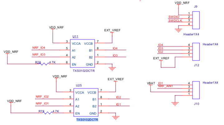
Regarding the 1.8v operation of SGP30, have a look on the schematic here.
As you can see there is a logic level shifter in between IO1 and IO2 which is connected to your SGP30 and the NRF_IO1 and NRF_IO2 which is connected to the NRF52840. The idea here is that you can interface sensors that are not 1.8v. External devices are usually in 3.3v and 5v.
Now, shorting VDD_NRF to EXT_VREF will make you out of spec of TXS0102DCTR logic level shifter. Because the VCCA and VCCB side has different voltage levels.
VCCB won’t allow 1.8V. It might work for a while probably but anything out of specs means the operation can be guaranteed.
Here’s a small portion of the datasheet that shows the voltage of operation of VCCA side and VCCB side. You can check the full datasheet on the link I posted on my previous post.
Two things I will do if I am in your case, (1) put some serial logs inside the SGP30 library then use serial terminal software that can log serial output automatically like CoolTerm. I can capture issues that occur erratically because the software will just continue to logging the serial output. I will see where is the last point before it stops. (2) Get the logic signal levels of the I2C lines to see the voltage levels are in good shape as well as check if there are bad slew rate on signals (if any).
This is helping… Considering that the intent of the TXS0102DCTR is to connect w/ external devices using 3.3v/5v, and that my device is out of spec, I’ll modify my device to use a higher voltage.
What I’m stuck on is the actual connection of an external sensor. Assuming I have a device that is 3.3v, I can use IO1 and IO2 for SCL/SCA. Then connect my ground to the board ground.
For power I would connect to the VBAT and my device would take the 4.x volts and convert it to what I need (3.3v). Do I then connect VBAT to EXT_VREF or do I connect my voltage (3.3v) to the EXT_VREF?
The RAK5010 is doing everything I need it to do except this final connection to an external I2C device. If I get the connections right to use a 3.3v I2C device I think that’ll make it all work reliability for me.