Details: I want to use an ext LED to indicate low battery status. However, i am not sure which IO pin I can connect to? From the J12 pinout, there are IO 1-4. But from the schematic, it shows that they are connected to the SIM module. Can someone help?
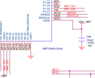
The IO 1-4 are not connected to SIM module. They are connected to a logic-level shifter then to NRF52840. Here’s the schematic connection. They are named NRF_IO1 to NRF_IO4.
What is the pin assignment? In number format? Eg. Is pin 20, IO2?
I have tried to connect an LED to the pin 20 and done a simple test, but LED still doesnt light up, as the voltage at pin 20 is still read as 0V.
 pinMode(20, OUTPUT);
 digitalWrite((20,HIGH);
LED is fine, verified connecting between gnd and Vref.
I missed that part. Vref is not connected to anything at this moment. Can i connect Vbat to Vref ?I do not want to connect any other source to the RAK to make it compact.