Hey guys,
I’m fairly new to this stuff so be easy with me!
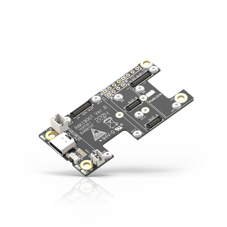
I’m having trouble with adding a remote USBc connection to a RAK19007 2nd gen base board. I have a simple 4 wire USBc extension that I would like to solder to the board without plugging the existing USBc connection. I would like to be able to have a data connection for it.
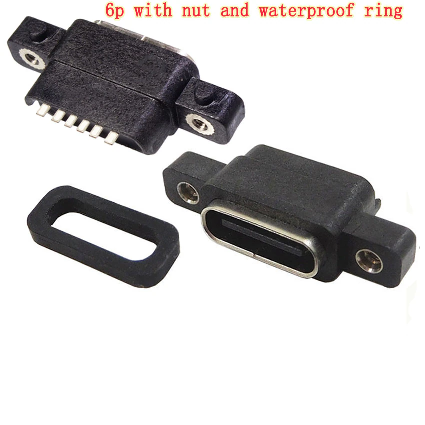
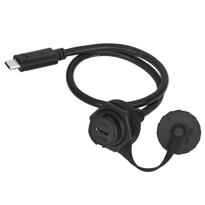
basically I have a case that has a water proof USBc connection on the outside. I would like to be able to connect to my computer and up date firmware and the like.
could someone point me in the proper direction for this. Im only seeing the IO slots for the connections.
From what I read 4 wires should be enough for a data connection? am I correct on that?
Hi bro,
4 wires is enough to load data.
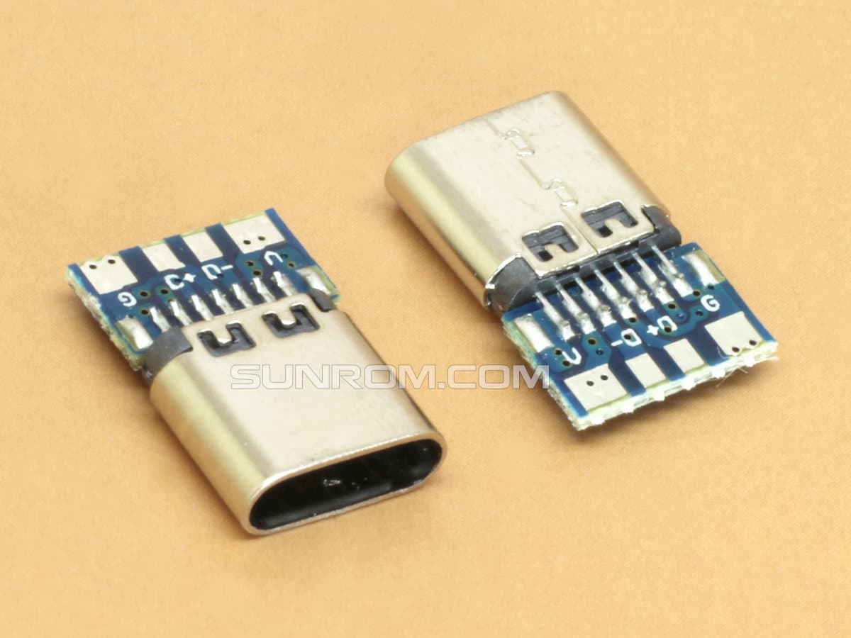
Even we only need 3 wires: D+, D-, GND.
Since you didn’t include pictures I can’t show you where you can solder the wire.
And my advice is to use a usb type C port because it is very difficult to solder wires to the circuit board, the points that can be soldered are very small and cannot be manipulated if you are not a professional in the matter. This.
Please use a type C connector to connect to an external USB.
So I’m assuming by what you said that there isn’t a good way to access those D+, D- connections with standard soldering outside of piggybacking off of the existing USBc connection.
Side note/Question. will connecting to just the D+ and D- along with GND allow charging or only data transmission?
that has a male USBc port on the back then I could build the case to allow for it to mount and then the board would slid into the USBc port before you screw it down and it would secure it.
cant seem to find a waterproof bulkhead fitting that has a male USBc port on the back though. hoping for a very inexpensive solution under $1USD each