Help with MQTT to Wifi

Hi,

I have a RAK 4631 with a RAK2305 WiFi board connected. I am using the example sketch ‘connect_ap’ to get WiFi connectivity, all which works fine.

What’s I’m trying to achieve is pushing data over Wifi to an MQTT server. There seem to be a ton of MQTT libraries available via the Arduino IDE. However, they all seem to require a Wifi ‘client’ object.

The example WiFi sketch is using AT commands to create the network connection, there’s no WiFi client object as such.

So… I have been looking at the EXPRESSIF documentation and I can see that there are AT commands to drive MQTT messaging, which I have been playing with (no joy so far).

My question(s) are:

  1. Is there a library to create a WiFi client for this board, which I could then use with some of the ‘off the shelf’ MQTT libraries?
  2. Can someone help me decipher why my AT commands for MQTT aren’t working…?

My current sketch is below, which is just the ap_connect example with what I think is the right MQTT AT command structure.

TIA!

/**
 * @file connect_ap.ino
 * @author Taylor lee ([email protected])
 * @brief connect a known AP and PING the IP "8.8.8.8" every 5 seconds
 *    Please see the detailed commands from
 *    https://docs.espressif.com/projects/esp-at/en/latest/AT_Command_Set/index.html
 * @version 0.1
 * @date 2020-07-28
 *
 * @copyright Copyright (c) 2020
 *
 * @note RAK4631 GPIO mapping to nRF52840 GPIO ports
   RAK4631    <->  nRF52840
   WB_IO1     <->  P0.17 (GPIO 17)
   WB_IO2     <->  P1.02 (GPIO 34)
   WB_IO3     <->  P0.21 (GPIO 21)
   WB_IO4     <->  P0.04 (GPIO 4)
   WB_IO5     <->  P0.09 (GPIO 9)
   WB_IO6     <->  P0.10 (GPIO 10)
   WB_SW1     <->  P0.01 (GPIO 1)
   WB_A0      <->  P0.04/AIN2 (AnalogIn A2)
   WB_A1      <->  P0.31/AIN7 (AnalogIn A7)
 */
#include <Wire.h>

#define WIFI_SSID "My-Wifi"
#define WIFI_PASSWORD "secretsquirrel"

/**
   @brief  execute at command
   @param  at: the at command you want to execute
   @param  expect: the respond you want to get
   @param  timeout: the timout of receive respond
*/
void execute_at(char *at, char *expect = NULL, int32_t timeout = 1000)
{
    String resp = "";

    Serial1.write(at);
    delay(10);

    while (timeout--)
    {
        if (Serial1.available())
        {
            resp += Serial1.readString();
        }
        delay(1);
    }

    Serial.println(resp);
    if (expect != NULL)
    {
        if (resp.indexOf(expect) != -1)
        {
            Serial.println("Execute OK.");
        }
        else
        {
            Serial.println("Execute Fail.");
        }
    }
    resp = "";
}

/**
   @brief Arduino setup function. Called once after power on or reset

*/
void setup()
{
    char cmd[128] = "";
    time_t timeout = millis();
    // Open serial communications and wait for port to open:
    Serial.begin(115200);
    while (!Serial)
    {
      if ((millis() - timeout) < 5000)
        {
            delay(100);
        }
        else
        {
            break;
        }
    }

    Serial.println("================================");
    Serial.println("RAK2305 WiFI example");
    Serial.println("================================");

    Serial1.begin(115200);
    delay(1000);

    // Set RAK2305 as AP and STA role
    execute_at("AT+CWMODE=3\r\n", "OK");

    // Set contry code
    execute_at("AT+CWCOUNTRY=0,\"AU\",1,13\r\n", "OK");

    // Connect AP with ssid and password
    snprintf(cmd, sizeof(cmd), "AT+CWJAP=\"%s\",\"%s\"\r\n", WIFI_SSID, WIFI_PASSWORD);
    execute_at(cmd, "OK");
}

/**
   @brief Arduino loop. Runs forever until power off or reset

*/
void loop()
{
    Serial1.println("AT+PING=\"8.8.8.8\"");
    // ping 8.8.8.8
     execute_at("AT+QPING=1,\"8.8.8.8\"\r\n", "OK");

     //execute_at("AT+MQTTUSERCFG=0,1,\"ESP32\",\"espressif\",\"1234567890\",0,0,\"");
     execute_at("AT+MQTTCONN=0,\"192.168.0.91\",1883,0");
     execute_at("AT+MQTTPUB=0,\"topic\",\"test\",1,0");
     execute_at("AT+MQTTCLEAN=0");
 
    delay(5000);
}

type or paste code here
Welcome to the forum @Wedgie32

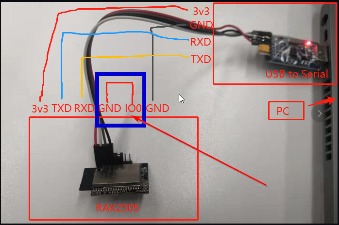
The default firmware on the RAK2305 does not support MQTT commands.
But you can reflash the RAK2305 with a different firmware that supports MQTT, but you will loose the BLE AT commands.

The file is on our WisBlock repo.
A tutorial is there as well => Burn firmware to RAK2305

Thank for the quick reply, that’s very helpful!

I have an Arduino Uno that I’m using as a USB to Serial converter, and I have the pinout/wires configured as I believe they should be, but the flash tool never seems to complete.

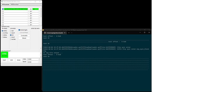
The ESP32 tool is configured as per this picture, and I have hit the Start button, I get a new ‘dot’ on the serial monitor on the right every second. But there’s no feedback from the download tool.

For the Arduino, I have the RESET and GND pins bridged (to make is a USB-Serial converter). I then have the wires connected to the ESP as per the tutorial.

What might I be missing?

Did you connect IO0 to GND and then do a reset of the RAk2305 or power cycle?


Without that the ESP32 does not go into bootloader mode and will not accept the new firmware.

Yes, I have a pin bridging GND and IO0 on the 2305. I’m power cycling the Arduino to ‘boot’ the system.

Do you have another USB-UART adapter? Could be your Arduino UNO is causing a problem.

Can you try to lower the baudrate from 912600 to 115200. Not sure if the Uno can cope with that high speed.

I am at a loss.

I bought a proper USB/Serial adapter and I have wired it up as described above, and I can’t make it do anything differently from my previous description. I’m assuming that it’s not going in to bootloader mode, but I don’t know why.
For reference, my USB to Serial converter is this:

I have the power switch on the adapter set to 3.3v.

:man_shrugging:

You can check if the RAk2305 goes into bootloader mode by using a terminal app and check the log output.

The ESP32 should report

ets Jun  8 2016 00:22:57

rst:0x1 (POWERON_RESET),boot:0x3 (DOWNLOAD_BOOT(UART0/UART1/SDIO_REI_REO_V2))
waiting for download

You should see the waiting for download message.

If you do not get any output on the terminal, try to switch RX and TX lines, check that your jumper wires are good connected.

But the RAK2305 works together with a RAK4631 Core module over UART, correct?

You can try the following (my last idea), that’s what I usually do.

  • Use the WisBlock Base board, plug only the RAK2305 into the Base Board. Remove the RAK4631 from the Base Board.
  • Connect the RX/TX/GND pins of the RAK2305 to you UART/USB adapter. DO NOT CONNECT 3.3V
  • Make the connection between IO0 and GND on the RAK2305.
  • Connect the UART/USB adapter to your computer and start the terminal app
  • Power up the Base Board, the RAK2305 should give some output over the UART/USB adapter.

If that works, and you see the waiting for download message, close the terminal app and start the Espressif flash tool.

Thanks again for your assistance. I got it working :slight_smile:

Long story short, the USB to Serial adapter I was using was running at 5.0v not 3.3v. I used an Arduino 3.3v output along with the USB/Serial adapter and I managed to get some sense out of the Serial console, then the firmware update worked perfectly.

This topic was automatically closed 2 days after the last reply. New replies are no longer allowed.