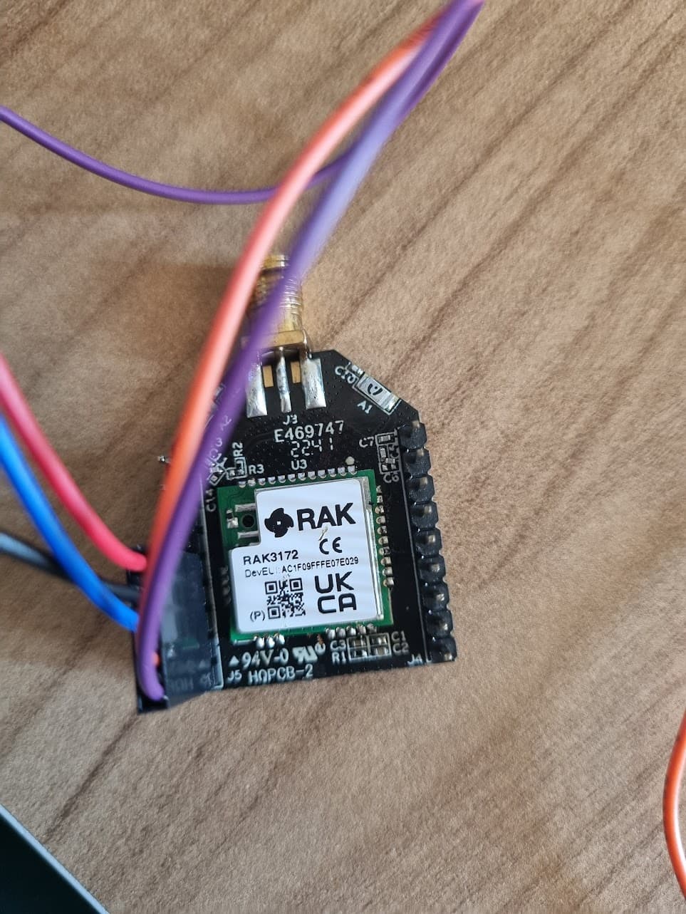
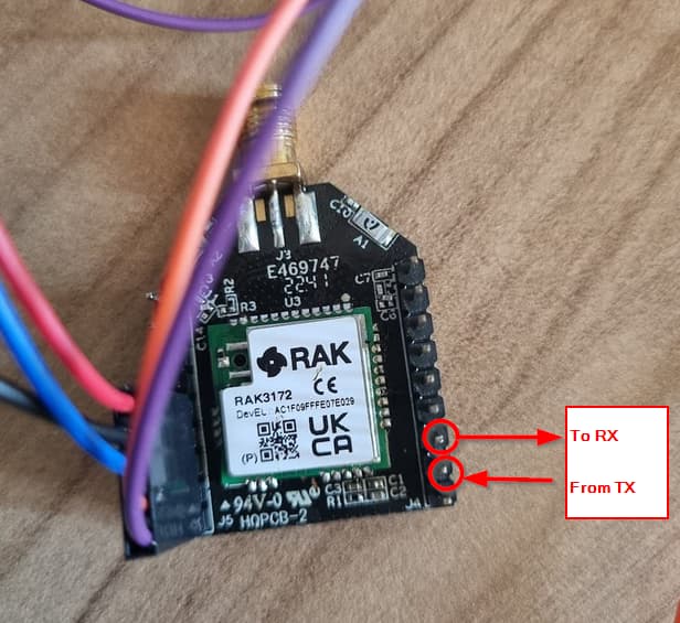
I bought RAK3172 modul (RAK3172H WisDuo LPWAN Module, 868MHz without IPEX) And I tried upload program. at first I have replaced rak3172 insted of RAK11720 Breakout Board to easy to reach pins and it looks like this:
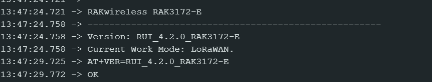
Actullay there was some problems for BOOT0 and RST pin buf after try and error firmware updated to latest one I can check over the uart1 from esp32. there is no problem.
I have measure the volt, 3v3 is applied there is no problem.
OUTPUT of Arduino ide
Performing 1200-bps touch reset on serial port COM7
Waiting for upload port...
No upload port found, using COM7 as fallback
"C:\Users\memet\AppData\Local\Arduino15\packages\rak_rui\tools\uploader_ymodem\1.0.1/uploader_ymodem.exe" -f "C:\Users\memet\AppData\Local\Temp\arduino\sketches\B1DE2EEB70DB979A724D3DFA6E8DB156/Arduino_Led_Breathing.ino.bin" -p COM7
Device is not in boot mode
Detecting baudrate..................
Detect baudrate fail, can not get the baudrate
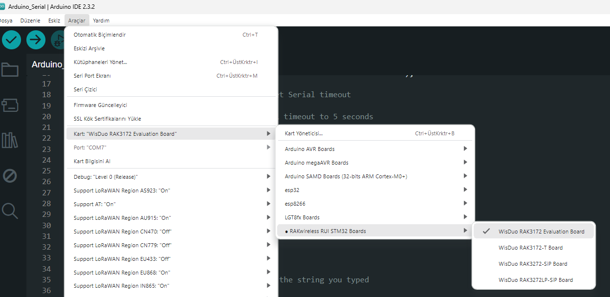
also I can not see the rak3172 in board list of arduino ide 2.3 so I try all 4 option
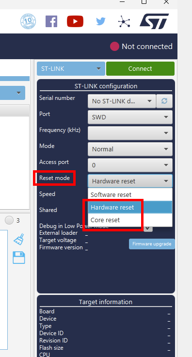
last one thing, What is the importance of BOOT0 and RST when flashing with STM32Cubeprogrammer or uploading a program on Arduino, and what is the correct sequence for them?
When you flash with Arduino, BOOT0 should not be touched.
BOOT0 is enabling the STM bootloader, but RUI3 has it’s own bootloader which is started with AT+BOOT (that is what Arduino uploader is sending to the device before it starts uploading).
When flashing with STM32CubeProgrammer over UART, you connect BOOT0 to VCC, then pull RST to GNS (short) to restart the MCU. Then it is in STM bootloader mode which is required by STM32CubeProgrammer.
I am not sure if that is required when you use the SWD interface with STM32CubeProgrammer (I don’t have one). But I think it is not required to use BOOT0 and RST at all.
I am using the SWD interface with JLink, and no additional actions on BOOT0 or RST are required.