There is NO LoRaWAN library in use here - just the library to drive the radio chip in LoRa mode. You need a LoRaWAN library like the MCCI LMiC.
but lorawan is from Gateway into the WAN, isnt it?
In the “LAN” ( nodes and sensors, and part of the gateway) is LoRa protocol, isnt it?
Thanks
LoRa is the radio transmission system.
LoRaWAN uses that radio transmission system to add a Media Access Layer - a specified sequence of bytes that relay the information & control messages.
You can send bytes like “48 65 6c 6c 6f 20 77 6f 72 6c 64” via LoRa to LoRa.
But there is no device identification, no encryption, no session, no counter, no headers, nothing that allows a gateway to know who it’s from & where to pass it on.
So, you can either continue to send LoRa packets out in to the wild OR you can get busy with a LoRaWAN library / stack.
Understood Nick.
Thanks a lot.
Have homework to do to understand and get ready to use LoRaWan.
Any video or written tutorial is wellcome.
Thanks a lot
Emilio
There should be plenty of example sketches for your particular node. Just google LMIC for it.
Regards
Vladislav
Thanks a lot Vladislav.
Thanks both.
Look it up, try and feedback
Brgds and saludos amigos!
Hi guys
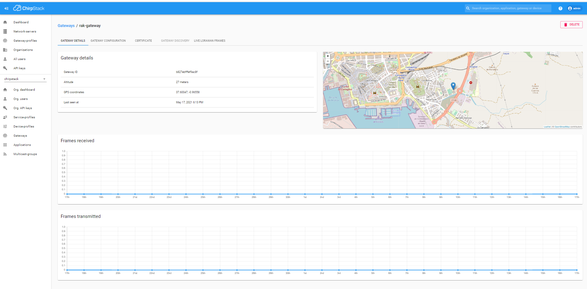
after much struggle just managed to connect my device to the RAK gateway.
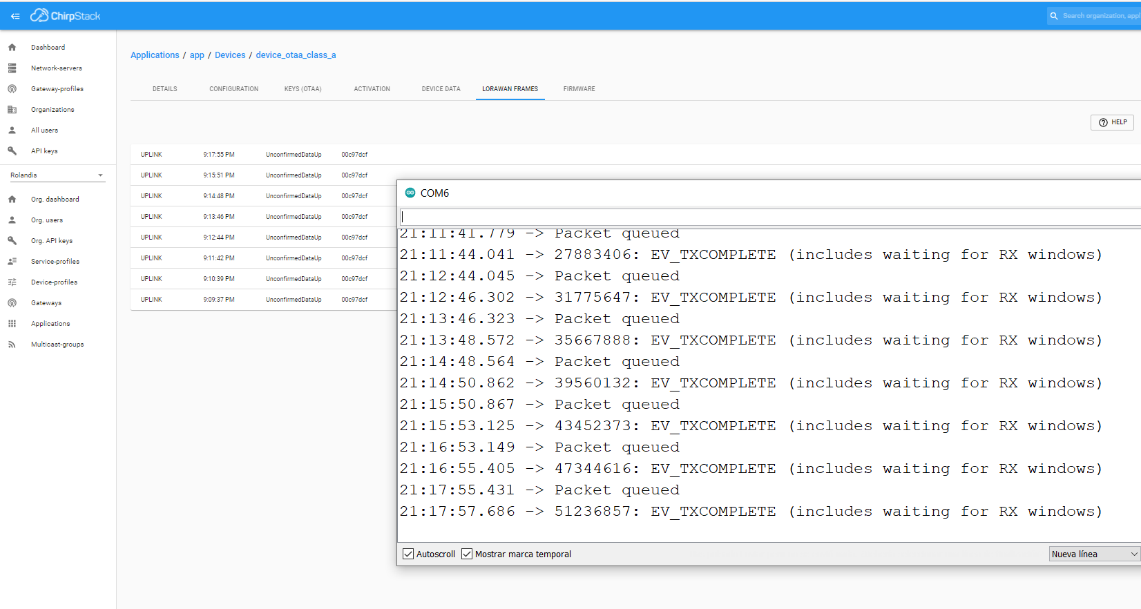
THere are issues though. Do not get the Hello World message from the sketch and it says: " unconfirmed dataup"
Can you help me on that? Almost there 
I have used IBM LMIC ttn otaa library renamed on behalf of my first contact:
/*******************************************************************************
-
Copyright (c) 2015 Thomas Telkamp and Matthijs Kooijman
-
Permission is hereby granted, free of charge, to anyone
-
obtaining a copy of this document and accompanying files,
-
to do whatever they want with them without any restriction,
-
including, but not limited to, copying, modification and redistribution.
-
NO WARRANTY OF ANY KIND IS PROVIDED.
-
This example sends a valid LoRaWAN packet with payload "Hello,
-
world!", using frequency and encryption settings matching those of
-
the The Things Network.
-
This uses OTAA (Over-the-air activation), where where a DevEUI and
-
application key is configured, which are used in an over-the-air
-
activation procedure where a DevAddr and session keys are
-
assigned/generated for use with all further communication.
-
Note: LoRaWAN per sub-band duty-cycle limitation is enforced (1% in
-
g1, 0.1% in g2), but not the TTN fair usage policy (which is probably
-
violated by this sketch when left running for longer)!
-
To use this sketch, first register your application and device with
-
the things network, to set or generate an AppEUI, DevEUI and AppKey.
-
Multiple devices can use the same AppEUI, but each device has its own
-
DevEUI and AppKey.
-
Do not forget to define the radio type correctly in config.h.
*******************************************************************************/
#include <lmic.h>
#include <hal/hal.h>
#include <SPI.h>
// This EUI must be in little-endian format, so least-significant-byte
// first. When copying an EUI from ttnctl output, this means to reverse
// the bytes. For TTN issued EUIs the last bytes should be 0xD5, 0xB3,
// 0x70.
static const u1_t PROGMEM APPEUI[8]={ 0x00, 0x00, 0x00, 0x00, 0x00, 0x00, 0x00, 0x00 };
void os_getArtEui (u1_t* buf) { memcpy_P(buf, APPEUI, 8);}
// This should also be in little endian format, see above.
static const u1_t PROGMEM DEVEUI[8]={ 0x5b, 0xb1, 0x7b, 0x37, 0xe7, 0x5e, 0xc1, 0x4b };
void os_getDevEui (u1_t* buf) { memcpy_P(buf, DEVEUI, 8);}
// This key should be in big endian format (or, since it is not really a
// number but a block of memory, endianness does not really apply). In
// practice, a key taken from ttnctl can be copied as-is.
// The key shown here is the semtech default key.
static const u1_t PROGMEM APPKEY[16] = { 0x2c, 0x2f, 0x6f, 0x96, 0x9d, 0xee, 0xc6, 0x84, 0x05, 0x1a, 0x8e, 0xf0, 0x76, 0x3e, 0x77, 0xa4 };
void os_getDevKey (u1_t* buf) { memcpy_P(buf, APPKEY, 16);}
static uint8_t mydata[] = “Hello, world!”;
static osjob_t sendjob;
// Schedule TX every this many seconds (might become longer due to duty
// cycle limitations).
const unsigned TX_INTERVAL = 60;
// Pin mapping
const lmic_pinmap lmic_pins = {
.nss = 18,
.rxtx = LMIC_UNUSED_PIN,
.rst = 23,
.dio = {26, 33, 32},
/// .dio = {2, 3, 4},
};
void onEvent (ev_t ev) {
Serial.print(os_getTime());
Serial.print(": ");
switch(ev) {
case EV_SCAN_TIMEOUT:
Serial.println(F(“EV_SCAN_TIMEOUT”));
break;
case EV_BEACON_FOUND:
Serial.println(F(“EV_BEACON_FOUND”));
break;
case EV_BEACON_MISSED:
Serial.println(F(“EV_BEACON_MISSED”));
break;
case EV_BEACON_TRACKED:
Serial.println(F(“EV_BEACON_TRACKED”));
break;
case EV_JOINING:
Serial.println(F(“EV_JOINING”));
break;
case EV_JOINED:
Serial.println(F(“EV_JOINED”));
        // Disable link check validation (automatically enabled
        // during join, but not supported by TTN at this time).
        LMIC_setLinkCheckMode(0);
        break;
    case EV_RFU1:
        Serial.println(F("EV_RFU1"));
        break;
    case EV_JOIN_FAILED:
        Serial.println(F("EV_JOIN_FAILED"));
        break;
    case EV_REJOIN_FAILED:
        Serial.println(F("EV_REJOIN_FAILED"));
        break;
        break;
    case EV_TXCOMPLETE:
        Serial.println(F("EV_TXCOMPLETE (includes waiting for RX windows)"));
        if (LMIC.txrxFlags & TXRX_ACK)
          Serial.println(F("Received ack"));
        if (LMIC.dataLen) {
          Serial.println(F("Received "));
          Serial.println(LMIC.dataLen);
          Serial.println(F(" bytes of payload"));
        }
        // Schedule next transmission
        os_setTimedCallback(&sendjob, os_getTime()+sec2osticks(TX_INTERVAL), do_send);
        break;
    case EV_LOST_TSYNC:
        Serial.println(F("EV_LOST_TSYNC"));
        break;
    case EV_RESET:
        Serial.println(F("EV_RESET"));
        break;
    case EV_RXCOMPLETE:
        // data received in ping slot
        Serial.println(F("EV_RXCOMPLETE"));
        break;
    case EV_LINK_DEAD:
        Serial.println(F("EV_LINK_DEAD"));
        break;
    case EV_LINK_ALIVE:
        Serial.println(F("EV_LINK_ALIVE"));
        break;
     default:
        Serial.println(F("Unknown event"));
        break;
}
}
void do_send(osjob_t* j){
// Check if there is not a current TX/RX job running
if (LMIC.opmode & OP_TXRXPEND) {
Serial.println(F(“OP_TXRXPEND, not sending”));
} else {
// Prepare upstream data transmission at the next possible time.
LMIC_setTxData2(1, mydata, sizeof(mydata)-1, 0);
Serial.println(F(“Packet queued”));
}
// Next TX is scheduled after TX_COMPLETE event.
}
void setup() {
Serial.begin(115200);
Serial.println(F(“Starting”));
#ifdef VCC_ENABLE
// For Pinoccio Scout boards
pinMode(VCC_ENABLE, OUTPUT);
digitalWrite(VCC_ENABLE, HIGH);
delay(1000);
#endif

// LMIC init
os_init();
// Reset the MAC state. Session and pending data transfers will be discarded.
LMIC_reset();

// Start job (sending automatically starts OTAA too)
do_send(&sendjob);
}
void loop() {
os_runloop_once();
}
I suspect there could still be a pin assignation problem, or a problem in my void Enqueue dowlink payload config:
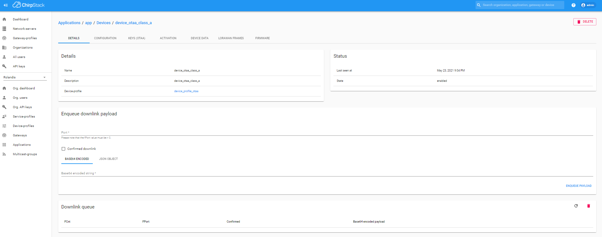
That’s normal. The payload will be encoded Base64 and probably appear on another layout.
What makes you suspect that?
What makes you suspect that? Particularly this bit, that’s for downlinks, not uplinks.
Hi Nick
thanks for your concern.
- How do I find the Hello World message in Base64 layout?
- Because my esp32 has like 7 versions and not completely sure how the sketch assigns the 3 pins of DIO according to my pinout.
- Because, If I understood right, for a proper communication, after every sending message from device, it needs a confirmation reception from gateway. And this Download queue I have not filled in
Hello, world! encoded as Base64 is SGVsbG8sIHdvcmxkIQ==
It’s more the other way round, you find out how the hardware is connecting the DIO pins and then tell the sketch in the pins section.
No, no, no, no, no, no, no. OMG, who told you that?
Confirmation links are rare. When your gateways transmits the ack it can not hear anything at all, so all other nodes may be transmitting but their uplink won’t get through.
And as an individual device, your gateway may then exceed your local legal limits.
We use confirmed uplinks when we HAVE to know the gateway heard it. Even then it doesn’t confirm that the entire backend has acted on the uplink.
Downlinks are completely the opposite - they are messages from you to the device, which you can also choose to have confirmed if you wish, but again should be used sparingly.
Thanks again Nick.
Clear no need for confirmation of node message.
What I need is now modify my sketch to send readings from a bmp pressure temperature sensor and be able to read and store it in Chirpstack.
If I modify the first contact sketch and include the bmp readings, where can I access and store it in Chirpstack?
Brgds
Emilio:
My ultimate goal is to implement a 14 node lorawan network with 7 sensors per node and store it in the internet, creating later a dashboard with grafana. All this is to be implemented in a lemon plantation in South east Spain in the coming 6 months as a company practice of my studies in technical school
Perhaps review the docs related to integrations and uplinks?
Yup!
I will look for them and study.
I have found my Hello World message!!! 
you have to press a little down arrow in Device Data in the Device!

Now I can be really happy for a minute!!!

Thanks!!!
Hello again guys
I managed to send node/device info from node to AWS SNS.
But I think there was a problem RAK could solve, and I say as feedback:
DNS server for the RAK7243 is not configured with the configuration protocol in web.
I had to do so using Putty linux commands and then I got access to AWS SNS
Before that, I could ping from Putty SSH connection to 8.8.8.8, but not to google.es
Nevertheless, my RAK 7243 is not valid for AWS IOT Core, so I must stop here and get a new RAK 7258 to do so.
Is that a proper gateway for handelling 14 nodes with 7 sensors each, 8 mobile esp32 sensors to track tractors, and 40 one month seasonal nodes for sending 2-3 photos per day each of citrus pest traps? All nodes being lora ESP32?
I will need 1 RAK 7258 to try and 4 to 14 more, if I succeed, so Vladislav, If can get a discount for the company let me know how do it.
Thanks for all your help. You have clarified my way a lot, and make me realise how some things work, that without your help would have stopped me.
REally, thank you both
Emilio
They both are, but if the sensors are outside, you could consider an outdoor gateway. Less than 70 devices would be no load at all for either, both of which could deal with 100’s if not 1000’s of devices.
What is it that stops the RAK7243 being valid for AWS IoT Core?
Given that most payloads are in the 20-50 byte range and there is an upper limit of ~222 bytes, you may not be able to pull a system together that sends pictures.
Hello Nick.
Thanks again dfor info.
It seems that what stops it is no having installed software Lora Basic Station. As far as I found out only 3 RAK gateways have it:
But it seems it is possible though with other gateways if you install Mosquito MQTT server, though seems more complicated and not so efficient for later needs in AWS:
https://aws.amazon.com/es/blogs/iot/how-to-bridge-mosquitto-mqtt-broker-to-aws-iot/
Best regards and thanks again
Emilio
But you could install the software …
Yes Nick, but seems There could be a problem to smoothly run lambda procedures in AWS that way, and after trying to use AWS AI services in our year of data collecting to produce agricultural forecasts
It seems that with RAK wisgate Edge compatibles model that is easier to avoid problems.
Thanks for concern
Regards
Emilio