Hello, I am working with the RAK5801 4-20mA interface board attached to Wisblock.
According to the documentation, it provides two 4-20mA inputs.
The top pin (Pin #8) maps to the A1 analog input, and the next pin (Pin #7) maps to the A0 input.
When I read these inputs, I am getting expected values from A1, but when I read A0, it is always approximately 600 (integer), no matter what is connected, or disconnected.
A1 goes to zero when disconnected, but A0 stays at ~600.
Is there some sort of additional initialization necessary to enable this input?
In the setup() function I initialize both pins like this:
pinMode(WB_A1, INPUT);
pinMode(WB_A0, INPUT);
I ensure to power on the RAK5801 by this:
pinMode(WB_IO1, OUTPUT);
digitalWrite(WB_IO1, HIGH);
delay(1000); // Give peripherals time to stabilize before reading
AN1 is useable by default. But if you need to use AN0, there are few hardware modifications needed to configure it correctly because AN0 is being used by default to measure the battery voltage.
Btw, on using Analog Input, you don’t need to configure the pinMode.
@carlrowan Thank you so much for your reply. Can you please elaborate on how to do the hardware modifications? I need to monitor two 4-20mA process loops with the single Wisblock unit (pressure and temperature) and this would be incredibly helpful.
Very simple solution I just found. Please test.
The A0 of the 4-20mA interface is connected to IO4 of WisBlock.
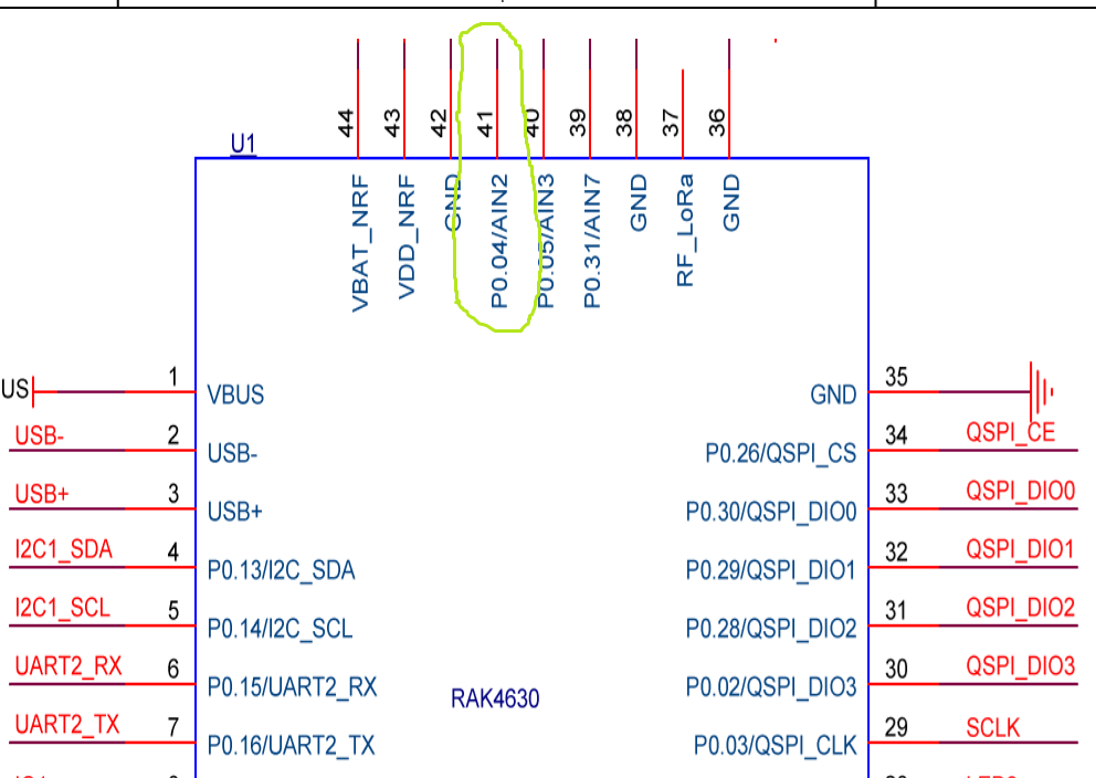
The RAK4631 has IO 4 connected to GPIO P0.04/AIN2.
It should be possible to read A0 (4-20mA) on Ain2 of the RAK4630.
analogRead(WB_IO4);
Just make sure you don’t use IO4 for anything else.
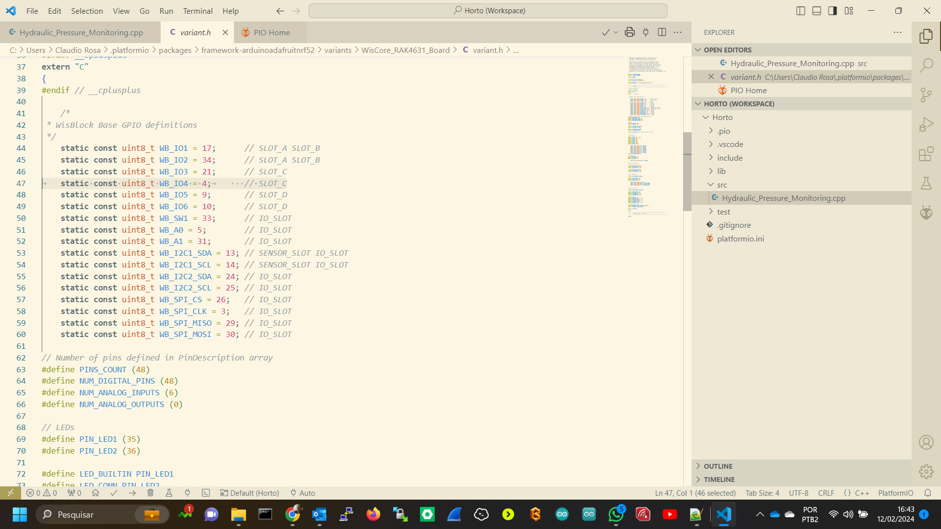
Doing a double check in the RAK4631-R documentation, I found some things different that you wrote in the article: I am seeing pin 41 instead of pin 4 in the variant.h file.
Could you help me to understand what is the right value?
Pin numbers and GPIO numbers are two very different things.
Pin number 41 is used when you make a PCB layout. The MCU doesn’t know what pin 41 means.
GPIO number is the output port of the MCU, in this case GPIO4 on the WisBlock Base Board is connected to the GPIO 0.04 of the MCU. So if you want to set IO4 to high or low, you have to use the 04, not the 41.
Easier (and that’s why they are predefined in the BSP) is to forget about pin numbers and GPIO numbers and use
WB_IO1
WB_IO2
WB_IO3
…
in your code.
You can find all definitions in the variant.h file in the BSP.
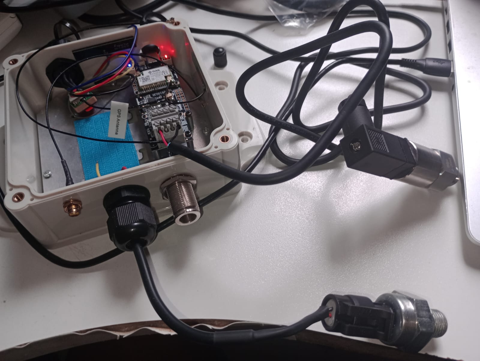
I found the problem in the transducer, I had connected the wire red (vcc) and black (ground), instead red and green (signal). Take a look in my picture