I am very new to LoRa and am in the weeds a bit. I have been able to successfully setup my ESP32 to transmit messages to my Wisgate Edge Lite 2/RAK7268. Now I would like to try and send messages TO my ESP32.
I’m confused on:
- If my code below is even setup to receive messages? I borrowed this code from a Sparkfun tutotial. I see there is a
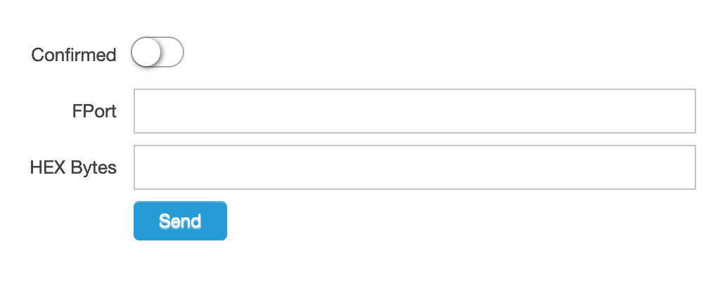
EV_TXCOMPLETEbut I’m not sure if it is being called. - How to properly send a message from the RAK software. I see the only fields are FPort and HEX Bytes. I’m not sure what FPort is used for, and I’m unclear on how to send a message within HEX Bytes?
I know this is quite a vague post but as I stated I’m pretty new to this all. Any pointers appreciated
Arduino Code:
#include <lmic.h>
#include <hal/hal.h>
#include <SPI.h>

// Below sets the trigger for sending a new message to a gateway.
// Either or both can be enabled (in which case pressing the button will restart the timer)
#define SEND_BY_BUTTON 1  // Send a message when button "0" is pressed
#define SEND_BY_TIMER 1 // Send a message every TX_INTERVAL seconds


// This function is intended to compensate for clock inaccuracy (up to ±10% in this example)
LMIC_setClockError(MAX_CLOCK_ERROR * 10 / 100);

// LoRaWAN NwkSKey, network session key
// This is the default Semtech key, which is used by the early prototype TTN
// network.
static const PROGMEM u1_t NWKSKEY[16] = { 0xd6, 0x24, 0x87, 0x05, 0x0f, 0x2d, 0x80, 0x7e, 0xac, 0x85, 0x0f, 0x62, 0xbc, 0x3a, 0xe8, 0x43 };

// LoRaWAN AppSKey, application session key
// This is the default Semtech key, which is used by the early prototype TTN
// network.
static const u1_t PROGMEM APPSKEY[16] = { 0x0f, 0xb0, 0x89, 0xd1, 0xb5, 0x00, 0x53, 0x01, 0xaa, 0x11, 0xf2, 0x0a, 0x71, 0xd2, 0xaa, 0x46 };

// LoRaWAN end-device address (DevAddr)
static const u4_t DEVADDR = 0x0123456789;

// These callbacks are only used in over-the-air activation, so they are
// left empty here (we cannot leave them out completely unless
// DISABLE_JOIN is set in config.h, otherwise the linker will complain).
void os_getArtEui (u1_t* buf) { }
void os_getDevEui (u1_t* buf) { }
void os_getDevKey (u1_t* buf) { }

static uint8_t mydata[] = "Hello, world!";
static osjob_t sendjob;

// Pin mapping for the SparkX ESP32 LoRa 1-CH Gateway
const lmic_pinmap lmic_pins = {
  .nss = 16,
  .rxtx = LMIC_UNUSED_PIN,
  .rst = 5,
  .dio = {26, 33, 32},
};

// If send-by-timer is enabled, define a tx interval
#ifdef SEND_BY_TIMER
#define TX_INTERVAL 60 // Message send interval in seconds
#endif

// State machine event handler
void onEvent (ev_t ev) {
  Serial.print(os_getTime());
  Serial.print(": ");
  switch (ev) {
    case EV_SCAN_TIMEOUT:
      Serial.println(F("EV_SCAN_TIMEOUT"));
      break;
    case EV_BEACON_FOUND:
      Serial.println(F("EV_BEACON_FOUND"));
      break;
    case EV_BEACON_MISSED:
      Serial.println(F("EV_BEACON_MISSED"));
      break;
    case EV_BEACON_TRACKED:
      Serial.println(F("EV_BEACON_TRACKED"));
      break;
    case EV_JOINING:
      Serial.println(F("EV_JOINING"));
      break;
    case EV_JOINED:
      Serial.println(F("EV_JOINED"));
      break;
    case EV_RFU1:
      Serial.println(F("EV_RFU1"));
      break;
    case EV_JOIN_FAILED:
      Serial.println(F("EV_JOIN_FAILED"));
      break;
    case EV_REJOIN_FAILED:
      Serial.println(F("EV_REJOIN_FAILED"));
      break;
    case EV_TXCOMPLETE:
      digitalWrite(LED_BUILTIN, LOW); // Turn off LED after send is complete
      Serial.println(F("EV_TXCOMPLETE (includes waiting for RX windows)"));
      if (LMIC.txrxFlags & TXRX_ACK)
        Serial.println(F("Received ack"));
      if (LMIC.dataLen) {
        Serial.println(F("Received "));
        Serial.println(LMIC.dataLen);
        Serial.println(F(" bytes of payload"));
      }
#ifdef SEND_BY_TIMER
      // Schedule the next transmission
      os_setTimedCallback(&sendjob, os_getTime() + sec2osticks(TX_INTERVAL), do_send);
#endif
      break;
    case EV_LOST_TSYNC:
      Serial.println(F("EV_LOST_TSYNC"));
      break;
    case EV_RESET:
      Serial.println(F("EV_RESET"));
      break;
    case EV_RXCOMPLETE:
      // data received in ping slot
      Serial.println(F("EV_RXCOMPLETE"));
      break;
    case EV_LINK_DEAD:
      Serial.println(F("EV_LINK_DEAD"));
      break;
    case EV_LINK_ALIVE:
      Serial.println(F("EV_LINK_ALIVE"));
      break;
    default:
      Serial.println(F("Unknown event"));
      break;
  }
}

// Transmit data from mydata
void do_send(osjob_t* j) {
  // Check if there is not a current TX/RX job running
  if (LMIC.opmode & OP_TXRXPEND) {
    Serial.println(F("OP_TXRXPEND, not sending"));
  } else {
    digitalWrite(LED_BUILTIN, HIGH); // Turn on LED while sending
    // Prepare upstream data transmission at the next possible time.
    LMIC_setTxData2(1, mydata, sizeof(mydata) - 1, 0);
    Serial.println(F("Packet queued"));
  }
}

void setup() {
  Serial.begin(115200);

  // Set button pin as input
#ifdef SEND_BY_BUTTON
  pinMode(0, INPUT);
#endif
  // Configure built-in LED -- will illuminate when sending
  pinMode(LED_BUILTIN, OUTPUT);
  digitalWrite(LED_BUILTIN, LOW);

  // LMIC init
  os_init();
  // Reset the MAC state. Session and pending data transfers will be discarded.
  LMIC_reset();

  // Set static session parameters. Instead of dynamically establishing a session
  // by joining the network, precomputed session parameters are be provided.
  uint8_t appskey[sizeof(APPSKEY)];
  uint8_t nwkskey[sizeof(NWKSKEY)];
  memcpy_P(appskey, APPSKEY, sizeof(APPSKEY));
  memcpy_P(nwkskey, NWKSKEY, sizeof(NWKSKEY));
  LMIC_setSession (0x1, DEVADDR, nwkskey, appskey);

  // Instead of using selectSubBand, which will cycle through a sub-band of 8
  // channels. We'll configure the device to only use one frequency.
  // First disable all sub-bands
  for (int b = 0; b < 8; ++b) {
    LMIC_disableSubBand(b);
  }
  // Then enable the channel(s) you want to use
  LMIC_enableChannel(8); // 903.9 MHz

  // Disable link check validation
  LMIC_setLinkCheckMode(0);

  // TTN uses SF9 for its RX2 window.
  LMIC.dn2Dr = DR_SF9;

  // Set data rate and transmit power for uplink (note: txpow seems to be ignored by the library)
  LMIC_setDrTxpow(DR_SF7, 14);

  // Start job -- Transmit a message on begin
  do_send(&sendjob);
}

void loop() {
  os_runloop_once();
#ifdef SEND_BY_BUTTON
  if (digitalRead(0) == LOW) {
    while (digitalRead(0) == LOW) ;
    do_send(&sendjob);
  }
#endif
}
RAK UI for sending a downlink message: