/* USER CODE BEGIN Header */
/**
******************************************************************************
* @file : main.c
* @brief : Main program body
******************************************************************************
* @attention
*
* Copyright (c) 2024 STMicroelectronics.
* All rights reserved.
*
* This software is licensed under terms that can be found in the LICENSE file
* in the root directory of this software component.
* If no LICENSE file comes with this software, it is provided AS-IS.
*
******************************************************************************
*/
/* USER CODE END Header */
/* Includes ------------------------------------------------------------------*/
#include "main.h"
/* Private includes ----------------------------------------------------------*/
/* USER CODE BEGIN Includes */
#include <string.h>
#include<stdio.h>
/* 버퍼의 크기를 변경 */
#define UART_BUFFER_SIZE 128
#define uart &huart1
/* USER CODE END Includes */
/* Private typedef -----------------------------------------------------------*/
/* USER CODE BEGIN PTD */
/* USER CODE END PTD */
/* Private define ------------------------------------------------------------*/
/* USER CODE BEGIN PD */
/* USER CODE END PD */
/* Private macro -------------------------------------------------------------*/
/* USER CODE BEGIN PM */
/* USER CODE END PM */
/* Private variables ---------------------------------------------------------*/
UART_HandleTypeDef huart1;
/* USER CODE BEGIN PV */
/* USER CODE END PV */
/* Private function prototypes -----------------------------------------------*/
void SystemClock_Config(void);
static void MX_GPIO_Init(void);
static void MX_USART1_UART_Init(void);
/* USER CODE BEGIN PFP */
/* USER CODE END PFP */
/* Private user code ---------------------------------------------------------*/
/* USER CODE BEGIN 0 */
typedef struct
{
unsigned char buffer[UART_BUFFER_SIZE];
volatile unsigned int head;
volatile unsigned int tail;
} ring_buffer;
ring_buffer rx_buffer = { { 0 }, 0, 0};
ring_buffer tx_buffer = { { 0 }, 0, 0};
ring_buffer *_rx_buffer;
ring_buffer *_tx_buffer;
char buffer[UART_BUFFER_SIZE];
int flag=0;
int startflag=1;
/* 링 버퍼를 초기화 */
void Ringbuf_init(void)
{
_rx_buffer = &rx_buffer;
_tx_buffer = &tx_buffer;
/* UART 오류 인터럽트 활성화: (프레임 오류, 노이즈 오류, 오버런 오류) */
__HAL_UART_ENABLE_IT(uart, UART_IT_ERR);
/* UART 데이터 레지스터가 비어 있지 않음 인터럽트 활성화 */
__HAL_UART_ENABLE_IT(uart, UART_IT_RXNE);
}
/* rx_buffer에 있는 데이터를 읽고 rx_buffer에 있는 tail count를 증가시킴 */
int Uart_read(void)
{
// head가 tail보다 앞서 있으면 어떤 문자를 가지고 있다는 뜻
if(_rx_buffer->head == _rx_buffer->tail)
{
return -1;
}
else
{
unsigned char c = _rx_buffer->buffer[_rx_buffer->tail];
_rx_buffer->tail = (unsigned int)(_rx_buffer->tail + 1) % UART_BUFFER_SIZE;
return c;
}
}
/* tx_buffer에 데이터를 쓰고 tx_buffer의 헤드 카운트를 증가시킴 */
void Uart_write(int c)
{
if (c>=0)
{
int i = (_tx_buffer->head + 1) % UART_BUFFER_SIZE;
// 출력 버퍼가 가득 찼다면, 인터럽트 핸들러가 버퍼를 비울 때까지 기다리는 것 외에는 아무것도 없습니다.
// ???: return 0 here instead?
while (i == _tx_buffer->tail);
_tx_buffer->buffer[_tx_buffer->head] = (uint8_t)c;
_tx_buffer->head = i;
__HAL_UART_ENABLE_IT(uart, UART_IT_TXE); // UART 전송 인터럽트 활성화
}
}
void Uart_sendstring (const char *s)
{
while(*s) Uart_write(*s++);
}
/* rx_buffer에서 읽을 수 있는 데이터가 있는지 확인 */
int IsDataAvailable(void)
{
return (uint16_t)(UART_BUFFER_SIZE + _rx_buffer->head - _rx_buffer->tail) % UART_BUFFER_SIZE;
}
void store_char(unsigned char c, ring_buffer *buffer)
{
int i = (unsigned int)(buffer->head + 1) % UART_BUFFER_SIZE;
// 수신된 문자를 위치
// 꼬리 바로 앞에 저장해야 하는 경우(머리가 꼬리의 현재 위치로 이동한다는 의미), 버퍼가 오버플로우될 것입니다.
// 따라서 문자를 쓰거나 머리를 이동시키지 않습니다.
if(i != buffer->tail) {
buffer->buffer[buffer->head] = c;
buffer->head = i;
}
}
void Uart_isr (UART_HandleTypeDef *huart)
{
uint32_t isrflags = READ_REG(huart->Instance->SR);
uint32_t cr1its = READ_REG(huart->Instance->CR1);
/* DR이 비어 있지 않고 Rx Int가 활성화된 경우 */
if (((isrflags & USART_SR_RXNE) != RESET) && ((cr1its & USART_CR1_RXNEIE) != RESET))
{
/******************
* @note PE(패리티 오류), FE(프레이밍 오류), NE(노이즈 오류), ORE(오버런
* 오류) 및 IDLE(유휴 라인 감지) 플래그는 소프트웨어
* 순서에 의해 지워집니다. USART_SR 레지스터에 대한 읽기 작업과 USART_DR 레지스터에 대한 읽기
* 작업.
* @note RXNE 플래그는 USART_DR 레지스터를 읽어서 지울 수도 있습니다.
* @note TC 플래그는 소프트웨어 시퀀스에 의해서도 클리어될 수 있습니다: USART_SR 레지스터에 대한 읽기 작업과 USART_DR 레지스터에 대한 쓰기 작업.
* @note TXE 플래그는 USART_DR 레지스터에 쓰기를 통해서만 지워집니다.
*********************/
huart->Instance->SR; /* 상태 레지스터 읽기 */
unsigned char c = huart->Instance->DR; /* 데이터 레지스터 읽기 */
store_char (c, _rx_buffer); // 버퍼에 데이터 저장
return;
}
/*전송 데이터 레지스터가 비어 있어서 인터럽트가 발생하는 경우 */
if (((isrflags & USART_SR_TXE) != RESET) && ((cr1its & USART_CR1_TXEIE) != RESET))
{
if(tx_buffer.head == tx_buffer.tail)
{
// 버퍼가 비어 있으므로 인터럽트를 비활성화합니다.
__HAL_UART_DISABLE_IT(huart, UART_IT_TXE);
}
else
{
// 출력 버퍼에 더 많은 데이터가 있습니다. 다음 바이트를 보냅니다.
unsigned char c = tx_buffer.buffer[tx_buffer.tail];
tx_buffer.tail = (tx_buffer.tail + 1) % UART_BUFFER_SIZE;
/********************
* @note PE(패리티 오류), FE(프레이밍 오류), NE(노이즈 오류), ORE(오버런
* 오류) 및 IDLE(유휴 라인 감지) 플래그는 소프트웨어에 의해 지워집니다.
* 순서: USART_SR 레지스터에 대한 읽기 작업 후 USART_DR 레지스터에 대한 읽기
* 작업.
* @note RXNE 플래그는 USART_DR 레지스터에 대한 읽기 작업으로도 지워질 수 있습니다.
* @note TC 플래그는 소프트웨어 순서에 의해 지워질 수 있습니다.
* USART_SR 레지스터에 대한 읽기 작업 후 USART_DR 레지스터에 대한 쓰기 작업.
* @note TXE 플래그는 USART_DR 레지스터에 대한 쓰기 작업으로만 지워집니다.
*********************/
huart->Instance->SR;
huart->Instance->DR = c;
}
return;
}
}
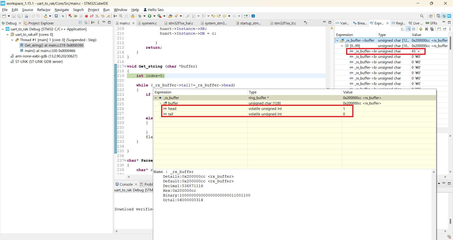
void Get_string (char *buffer)
{
int index=0;
while (_rx_buffer->tail!=_rx_buffer->head)
{
if ((_rx_buffer->buffer[_rx_buffer->head-1] == '\n'))
{
buffer[index] = Uart_read();
index++;
}
else
{
break;
}
flag=1;
}
}
char* Parse_string()
{
char* result;
result = strtok(buffer, ":");
for(int i=0;i<4;i++)
{
result = strtok(NULL, ":");
}
return result;
}
/* USER CODE END 0 */
/**
* @brief The application entry point.
* @retval int
*/
int main(void)
{
/* USER CODE BEGIN 1 */
/* USER CODE END 1 */
/* MCU Configuration--------------------------------------------------------*/
/* Reset of all peripherals, Initializes the Flash interface and the Systick. */
HAL_Init();
/* USER CODE BEGIN Init */
/* USER CODE END Init */
/* Configure the system clock */
SystemClock_Config();
/* USER CODE BEGIN SysInit */
/* USER CODE END SysInit */
/* Initialize all configured peripherals */
MX_GPIO_Init();
MX_USART1_UART_Init();
/* USER CODE BEGIN 2 */
Ringbuf_init();
/*
Uart_sendstring("at\r\n");
HAL_Delay(1000);//디버깅때 편의성을 위한 딜레이 함수
Uart_sendstring("at+nwm=0\r\n");
HAL_Delay(1000);//디버깅때 편의성을 위한 딜레이 함수
Uart_sendstring("at+pfreq=914000000\r\n");
HAL_Delay(1000);//디버깅때 편의성을 위한 딜레이 함수
Uart_sendstring("at+psf=6\r\n");
HAL_Delay(1000);//디버깅때 편의성을 위한 딜레이 함수
Uart_sendstring("at+pbw=500\r\n");
Get_string(buffer);
HAL_Delay(3000);//디버깅때 편의성을 위한 딜레이 함수
HAL_Delay(1000);//디버깅때 편의성을 위한 딜레이 함수
Uart_sendstring("at+pcr=0\r\n");
HAL_Delay(1000);//디버깅때 편의성을 위한 딜레이 함수
Uart_sendstring("at+ppl=8\r\n");
HAL_Delay(1000);//디버깅때 편의성을 위한 딜레이 함수
Uart_sendstring("at+ptp=22\r\n");
HAL_Delay(1000);//디버깅때 편의성을 위한 딜레이 함수
Uart_sendstring("at+precv=65535\r\n");
HAL_Delay(1000);//디버깅때 편의성을 위한 딜레이 함수
Get_string(buffer);
HAL_Delay(3000);//디버깅때 편의성을 위한 딜레이 함수
*/
flag=0;
memset(buffer,'\0',UART_BUFFER_SIZE);
/* USER CODE END 2 */
/* Infinite loop */
/* USER CODE BEGIN WHILE */
while (1)
{
/* USER CODE END WHILE */
/* USER CODE BEGIN 3 */
HAL_Delay(3000);//디버깅때 편의성을 위한 딜레이 함수
Get_string(buffer);
if(flag)
{
if(Parse_string()=="11")
HAL_GPIO_WritePin(LD2_GPIO_Port, LD2_Pin, GPIO_PIN_SET);
else
HAL_GPIO_WritePin(LD2_GPIO_Port, LD2_Pin, GPIO_PIN_RESET);
Uart_sendstring("at+precv=65535\r\n");
Get_string(buffer);
flag=0;
memset(buffer,'\0',UART_BUFFER_SIZE);
}
}
/* USER CODE END 3 */
}
/**
* @brief System Clock Configuration
* @retval None
*/
void SystemClock_Config(void)
{
RCC_OscInitTypeDef RCC_OscInitStruct = {0};
RCC_ClkInitTypeDef RCC_ClkInitStruct = {0};
/** Initializes the RCC Oscillators according to the specified parameters
* in the RCC_OscInitTypeDef structure.
*/
RCC_OscInitStruct.OscillatorType = RCC_OSCILLATORTYPE_HSI;
RCC_OscInitStruct.HSIState = RCC_HSI_ON;
RCC_OscInitStruct.HSICalibrationValue = RCC_HSICALIBRATION_DEFAULT;
RCC_OscInitStruct.PLL.PLLState = RCC_PLL_ON;
RCC_OscInitStruct.PLL.PLLSource = RCC_PLLSOURCE_HSI_DIV2;
RCC_OscInitStruct.PLL.PLLMUL = RCC_PLL_MUL16;
if (HAL_RCC_OscConfig(&RCC_OscInitStruct) != HAL_OK)
{
Error_Handler();
}
/** Initializes the CPU, AHB and APB buses clocks
*/
RCC_ClkInitStruct.ClockType = RCC_CLOCKTYPE_HCLK|RCC_CLOCKTYPE_SYSCLK
|RCC_CLOCKTYPE_PCLK1|RCC_CLOCKTYPE_PCLK2;
RCC_ClkInitStruct.SYSCLKSource = RCC_SYSCLKSOURCE_PLLCLK;
RCC_ClkInitStruct.AHBCLKDivider = RCC_SYSCLK_DIV1;
RCC_ClkInitStruct.APB1CLKDivider = RCC_HCLK_DIV2;
RCC_ClkInitStruct.APB2CLKDivider = RCC_HCLK_DIV1;
if (HAL_RCC_ClockConfig(&RCC_ClkInitStruct, FLASH_LATENCY_2) != HAL_OK)
{
Error_Handler();
}
}
/**
* @brief USART1 Initialization Function
* @param None
* @retval None
*/
static void MX_USART1_UART_Init(void)
{
/* USER CODE BEGIN USART1_Init 0 */
/* USER CODE END USART1_Init 0 */
/* USER CODE BEGIN USART1_Init 1 */
/* USER CODE END USART1_Init 1 */
huart1.Instance = USART1;
huart1.Init.BaudRate = 115200;
huart1.Init.WordLength = UART_WORDLENGTH_8B;
huart1.Init.StopBits = UART_STOPBITS_1;
huart1.Init.Parity = UART_PARITY_NONE;
huart1.Init.Mode = UART_MODE_TX_RX;
huart1.Init.HwFlowCtl = UART_HWCONTROL_NONE;
huart1.Init.OverSampling = UART_OVERSAMPLING_16;
if (HAL_UART_Init(&huart1) != HAL_OK)
{
Error_Handler();
}
/* USER CODE BEGIN USART1_Init 2 */
/* USER CODE END USART1_Init 2 */
}
/**
* @brief GPIO Initialization Function
* @param None
* @retval None
*/
static void MX_GPIO_Init(void)
{
GPIO_InitTypeDef GPIO_InitStruct = {0};
/* USER CODE BEGIN MX_GPIO_Init_1 */
/* USER CODE END MX_GPIO_Init_1 */
/* GPIO Ports Clock Enable */
__HAL_RCC_GPIOC_CLK_ENABLE();
__HAL_RCC_GPIOD_CLK_ENABLE();
__HAL_RCC_GPIOA_CLK_ENABLE();
__HAL_RCC_GPIOB_CLK_ENABLE();
/*Configure GPIO pin Output Level */
HAL_GPIO_WritePin(LD2_GPIO_Port, LD2_Pin, GPIO_PIN_RESET);
/*Configure GPIO pin : B1_Pin */
GPIO_InitStruct.Pin = B1_Pin;
GPIO_InitStruct.Mode = GPIO_MODE_IT_RISING;
GPIO_InitStruct.Pull = GPIO_NOPULL;
HAL_GPIO_Init(B1_GPIO_Port, &GPIO_InitStruct);
/*Configure GPIO pin : USART_TX_Pin */
GPIO_InitStruct.Pin = USART_TX_Pin;
GPIO_InitStruct.Mode = GPIO_MODE_AF_PP;
GPIO_InitStruct.Speed = GPIO_SPEED_FREQ_LOW;
HAL_GPIO_Init(USART_TX_GPIO_Port, &GPIO_InitStruct);
/*Configure GPIO pin : USART_RX_Pin */
GPIO_InitStruct.Pin = USART_RX_Pin;
GPIO_InitStruct.Mode = GPIO_MODE_INPUT;
GPIO_InitStruct.Pull = GPIO_NOPULL;
HAL_GPIO_Init(USART_RX_GPIO_Port, &GPIO_InitStruct);
/*Configure GPIO pin : LD2_Pin */
GPIO_InitStruct.Pin = LD2_Pin;
GPIO_InitStruct.Mode = GPIO_MODE_OUTPUT_PP;
GPIO_InitStruct.Pull = GPIO_NOPULL;
GPIO_InitStruct.Speed = GPIO_SPEED_FREQ_LOW;
HAL_GPIO_Init(LD2_GPIO_Port, &GPIO_InitStruct);
/* EXTI interrupt init*/
HAL_NVIC_SetPriority(EXTI15_10_IRQn, 0, 0);
HAL_NVIC_EnableIRQ(EXTI15_10_IRQn);
/* USER CODE BEGIN MX_GPIO_Init_2 */
/* USER CODE END MX_GPIO_Init_2 */
}
/* USER CODE BEGIN 4 */
/* USER CODE END 4 */
/**
* @brief This function is executed in case of error occurrence.
* @retval None
*/
void Error_Handler(void)
{
/* USER CODE BEGIN Error_Handler_Debug */
/* User can add his own implementation to report the HAL error return state */
__disable_irq();
while (1)
{
}
/* USER CODE END Error_Handler_Debug */
}
#ifdef USE_FULL_ASSERT
/**
* @brief Reports the name of the source file and the source line number
* where the assert_param error has occurred.
* @param file: pointer to the source file name
* @param line: assert_param error line source number
* @retval None
*/
void assert_failed(uint8_t *file, uint32_t line)
{
/* USER CODE BEGIN 6 */
/* User can add his own implementation to report the file name and line number,
ex: printf("Wrong parameters value: file %s on line %d\r\n", file, line) */
/* USER CODE END 6 */
}
#endif /* USE_FULL_ASSERT */
I’ll attach the code. I also need to check if there’s an issue with the function. Thank you for your response.