There are three sensors, RAK1902, RAK1901, and RAK12501 GPS.
RAK1902 is in slot b, 1901 slot A, and the GPS slot F, as per meshtastic docs.
I can’t see the GPS.
From documentation, slot F RXD1 should be CPU pin 34, and TXD1 should be CPU pin 33. Power control is IO5? So pin 37 on the CPU. Defaults didn’t work, so I am trying to determine if I have pin mappings correct.
Would that be the correct pins?
Should be no UART conflicts with the sensors in this configuration?
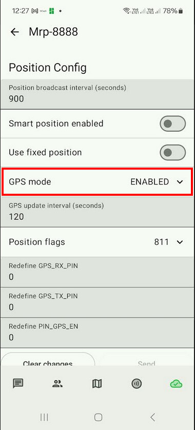
Power on for the GPS is via IO2 (GPIO34 in Meshtastic terms) and should be handled by Meshtastic automatically. Same for the UART pins, no need to change anything. The basic settings of Meshtastic work out of the box.
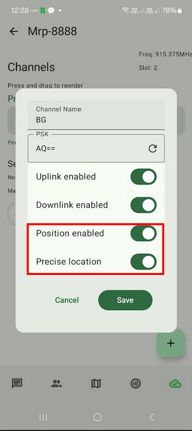
Oh yes, all enabled. Serial console never does show success in talking to the GPS module.
Curious, when looking at the schematics, for sensor slot F, on the 19001 base board, would the corresponding IO pins on the CPU for TXD1 RXD1 and IO5 be 33,34,37?
To rule out a hardware problem, please flash the attached WisBlock Hardware Test firmware from the UF2 file inside the ZIP file.
Check the output over USB and share it here please.
Here you go.
[APP] Initialize application
[EPD] Left LOW
[EPD] Middle LOW
[EPD] Right LOW
[EPD] Button status suggests no EPD
[EPD] No RAK14000 EPD
[SCAN] Found sensor at I2C1 0x3C
[SCAN] Found sensor at I2C1 0x5C
[SCAN] Found sensor at I2C1 0x70
[SCAN] Found 3 I2C devices
[GNSS] UBLOX did not answer on I2C, retry on Serial1
[GNSS] Initialize RAK1910
[GNSS] Try Serial 1
[GNSS] Try Serial 2
[GNSS] RAK1910/RAK12501 finished NOK
[FLASH] Flash Write-Read test #1
[FLASH] Flash Write-Read test #1 success
[FLASH] Read send time from flash 10000
[FLASH] Flash Write-Read test #2
[FLASH] Flash Write-Read test #2 success
[SX1262] SyncWord = 2414
[SX1262] LoRa transceiver ok
[APP] Battery 4.14 V
[APP] Timer wakeup
[APP] Battery 4.19 V
[APP] Send P2P packet
[APP] P2P TX finished