Hi,
We encountered related problems with the output data when using the combination of rak4630(L) Wisblock Core+rak19001 Wisblock Base+rak18032 ultrasonic sensors。
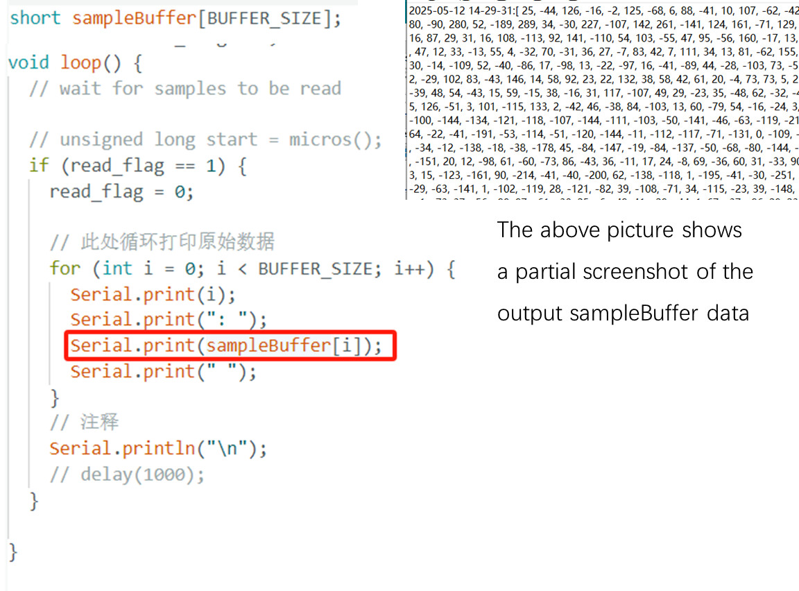
As shown in figure code snippet, we want to know, in HighRatePDMSerialPlotter. Ino example code, what is the output sampleBuffer data? According to our analysis, the sampleBuffer is defined as a short type, with each sample being 16 bits. However, the rak18032 outputs PDM data composed of 0 and 1. Therefore, the sampleBuffer should be converted from PDM to PCM data, meaning that the sampleBuffer is PCM data? Is this understanding correct? If correct, then at which step is the conversion from PDM data to PCM data carried out?
Secondly, we want to know what the data unit of sampleBuffer is? Can he be converted to dBuV units? How exactly should it be converted?
Hi,
You are correct that the microphone is outputting it’s data as a PCM stream. The nRF52 processor (on the RAK4631) has logic that does the conversion to a PDM stream. The buffers you see in the software are the result of this conversion within the processor to 16bit samples.
Hi,
Is what you said in the second sentence of the first paragraph wrong? Or did we misunderstand what you meant? Our view is that the RAK18032 ultrasonic sensor (with SPH0655LM4H-1 inside) outputs a PDM stream, and then the nRF52 processor (on the RAK4631) logically converts the PDM stream into a PCM stream. So the sampleBuffer (16-bit samples) in the code is actually a PCM stream. According to what you said, 16-bit samples is a PDM stream, but shouldn’t a PDM stream be a data stream composed of 0s and 1s?
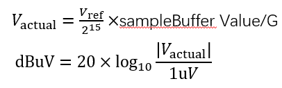
Currently, for the RAK18032 ultrasonic sensor, we directly output its sampleBuffer and then plot the ultrasonic time-domain graph. The horizontal coordinate represents time, and the vertical coordinate represents the value of the sampleBuffer. However, according to the project requirements, it needs to be the same as the professional equipment unit, and the vertical coordinate unit needs to be converted to the dBuV unit. Are there any good conversion methods here?
As shown in the figure, it is the formula for calculating the dBuV unit. For Vref, we take 3.3V, which is the supply voltage of rak18032. For sampleBuffer, it is the value printed by the sensor. For G, it is the gain, which is PDM.setGain(30) in the setup() function of the.ino file code. . We calculated according to this formula and found that there was a problem. It was not quite right when compared with professional equipment. When sampleBuffer=326, different professional devices output within the range of -2 to -7dBuV (calculated according to the formula in the figure, it is not within this range). When sampleBuffer=6445, the output of professional equipment should be around 60dBuV. Where is the problem with the formula?
Sorry you are correct - I swapped PDM and PCM in my reply :(. The microphone is a PDM stream which the nrF52 converts to PCM (16 bits).
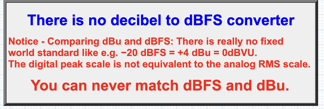
As I mentioned in my first reply, there is no conversion between the digital signal values (PCM 16 bits) and the analog dBuV (volts) values. Where did you find the formula you are using?
This is why you are having a hard time matching the dBuV (values) and DBFS (digital).
The SPH0655LM4H microphone on the RAK18032 does not use a Vref reference voltage as it’s not an analog microphone, but a MEMS microphone (using capacitive sensor technology).
You might be able to measure signals over the range and come up with your own formula, but it’s likely if you moved the audio source around it would not be consistent. (but you could try this if you want).