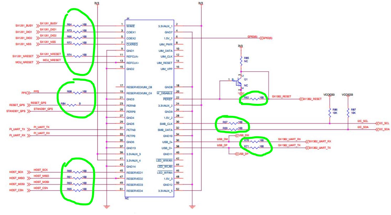
Hello, how are you? I am a Hardware Engineer and I am designing a PCB where I am going to use an mPCIe connector compatible with RAK2287 but reviewing the documentation I found that the schematic diagram has signals that need a resistance in series to the signal. Is it mandatory to consider these series resistors in the design? or can I just skip these resistors and make the connection directly?
The resistors really have to do with transmission line termination on your PC board layout.
You may also want to consider using carefully chosen ferrite beads to suppress RF harmonics of those signals.
It can be useful to give yourself more complex termination options on the SPI clock, for example both a series footprint and a shunt to ground footprint, and experiment to find what gives the best results.
Note that you only need the sx1261 signals if using the optional version which includes that chip.
The resistors on the GPS I2C and UART lines also serve a useful double duty as a way to make or break those conditions depending on the final system configuration you settle upon.
In short, definitely include a series element at the mPCIe connector and depending on the run at the SoC end as well. But if what you install on that footprint is a 0-ohm resistor or a low resistance or a ferrite bead or nothing is a decision you’ll probably want to defer until after you’ve worked with your first prototype.
A final note: you can’t individually control the mPCIe slot power if that SPI is shared with something else like your SoC’s boot flash, since an unpowered SX130x chip sitting on the bus will stop the powered SoC and flash from talking to each other. Fortuntately an inactive SX130x doesn’t consume that much power compared to the hosting system.
Thank you so much for the info Chris. I’m considering using a RaspberryPi 4B to control this module (RAK2287) and I’m going to use the SPI + GPIOs from RPI4. In addition to this I am considering a 3.3V to 3.3A power supply to power only the mPCIe connector. The mPCIe connector will only be used to communicate with the RAK2287 and the RPI4.
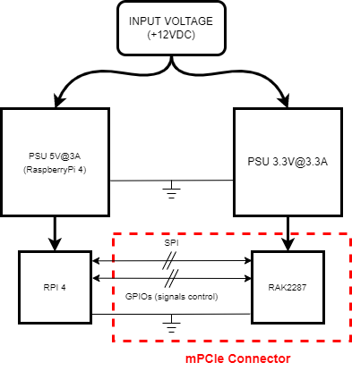
That sounds potentially problematic especially if it is a distinct mains supply - you have power sequencing concerns in that neither the pi nor the concentrator is supposed to be powered when the other is not, so you really want to be using a heft 5v supply and regulating the concentrator 3v3 from that.
Thanks Chris I’m considering and main input voltage of 12V. I have two blocks of power supply unit. The first PSU is to supply the RPI 4 and the second psu is to supply the mPCIe Connector, both PSU are connected at the same GND reference. I attach an image… Do you think there is a problem as you mentioned in the previous post?