There you can see the pins that are not connected. This is for the RAK2245 Concentration module inside the casing. There is however a pin header 40 to 40 RAK2245 to Rapberry Pi. Thus there are no available pin headers to be accessed. You would need to solder to the board. Which I would not recommend, plus how are you going to connect the relay, where is it going to stay.
I mean there are options, but could you please give more details on what exactly is the problem you are trying to solve?
Physically I have used a temporary solution to wire on GPIO pins (inserting wires in between male and female connectors, will do it for prototyping)
What I need to achieve:
The gateway is installed beside (20cm) a solenoid valve and a pressure switch (dry contact). It’s obvious that these two components are not be activated using LORA plus nodes, I want to wire and command this elements using GPIO.
Before sending LORA signals that activates multiple end devices, the program (Node Red in my case) needs I/O input condition from pressure switch, then needs to activate the solenoid valve trough a relay.
My question is:
on whitch available ports I could wire these two elements?
Is there an existing standard solution to use GPIO ports securely without inserting an extra layer (you are right, no soldering!)?
Thank you,
Bernard
Le mer. 19 juin 2019 à 11:05, Vladislav Yordanov via RAKwireless Forum [email protected] a écrit :
Hi @bernie2308.
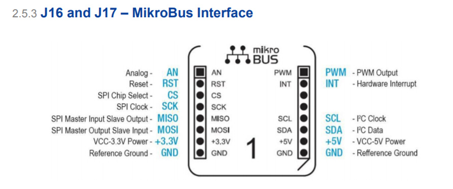
Very interesting situation As @Hobo mention soldering is not a good idea. If you using LTE version you can try to implement something via the MikroBus connector on the cellular board.
You can find pinouts of the RAK2013 module here RAK2013 User manual. And here is the speciffication of the MikroBus standart MikroBus.
To be honest i never used it, but we can try it
Hi @Velev,
Thank your for your interest in this case.
I can see in Design Guide on Comparison between
RAK831 & RAK2245 on RAK2245 pin# 7, 12, 13, 15, 16, 18, 22, 29, 31, 32, 36, 37, 38, 40 are free to use as GPIO, right?
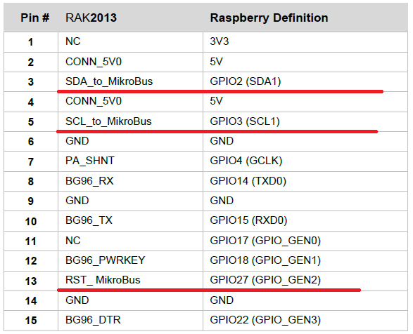
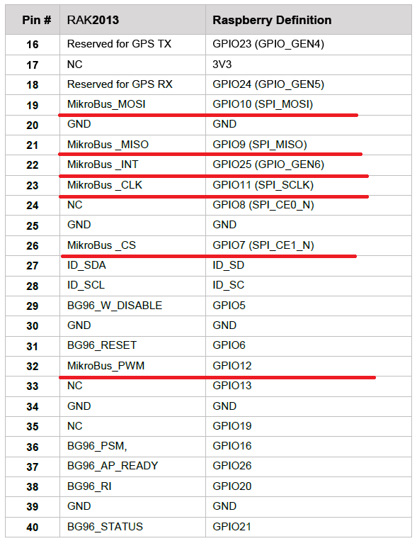
On RAK2013 User manual, I can see only pin# 11, 24, 33, 35 are free to use, right?
On Mikrobus, I could connect 5V DC and ground to power my relay?
I still dont know whitch GPIO I could use and where to connect it, knowing that I need one to ground my dry contact, and one to activate my relay…
HI @bernie2308
First of all is your gateway LTE version? If yes, you have Mikrobus on RAK2013 Cellular module.
On Mikrobus you have 3.3V and 5V pins.
Keep in mind to NOT connect relay directly to pins! You must add diode for the reverse current or in best way to have an optron (opto-isolator).
As described in document, pintouts are:
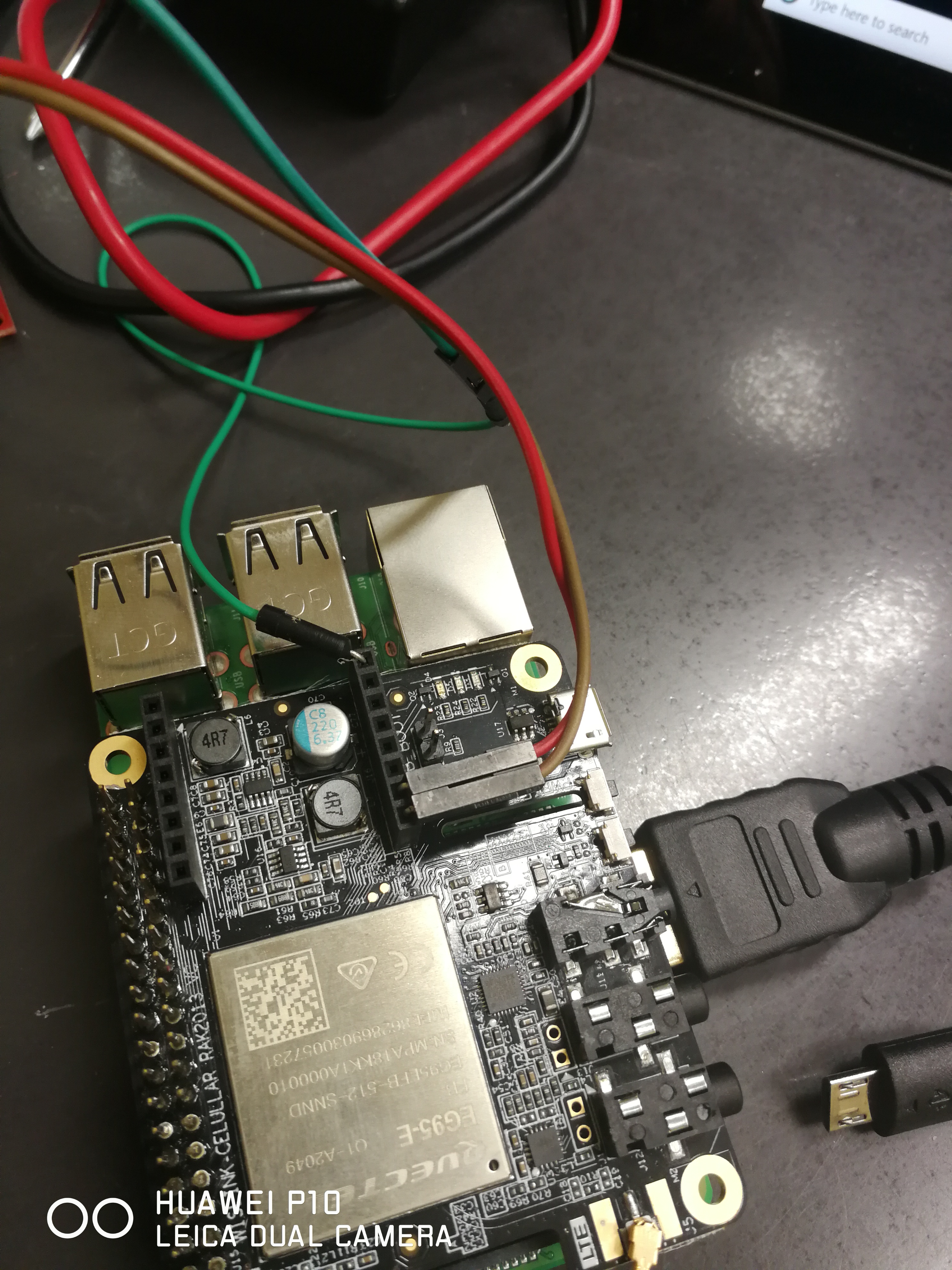
I just tried the solution @velev recommended. It works !
See the video below. You just need a script like the one here and make sure to connect the pins as in the picture - Red = VCC, Brown = GND, Green = GPIO12(PWM microBus)

 As
As