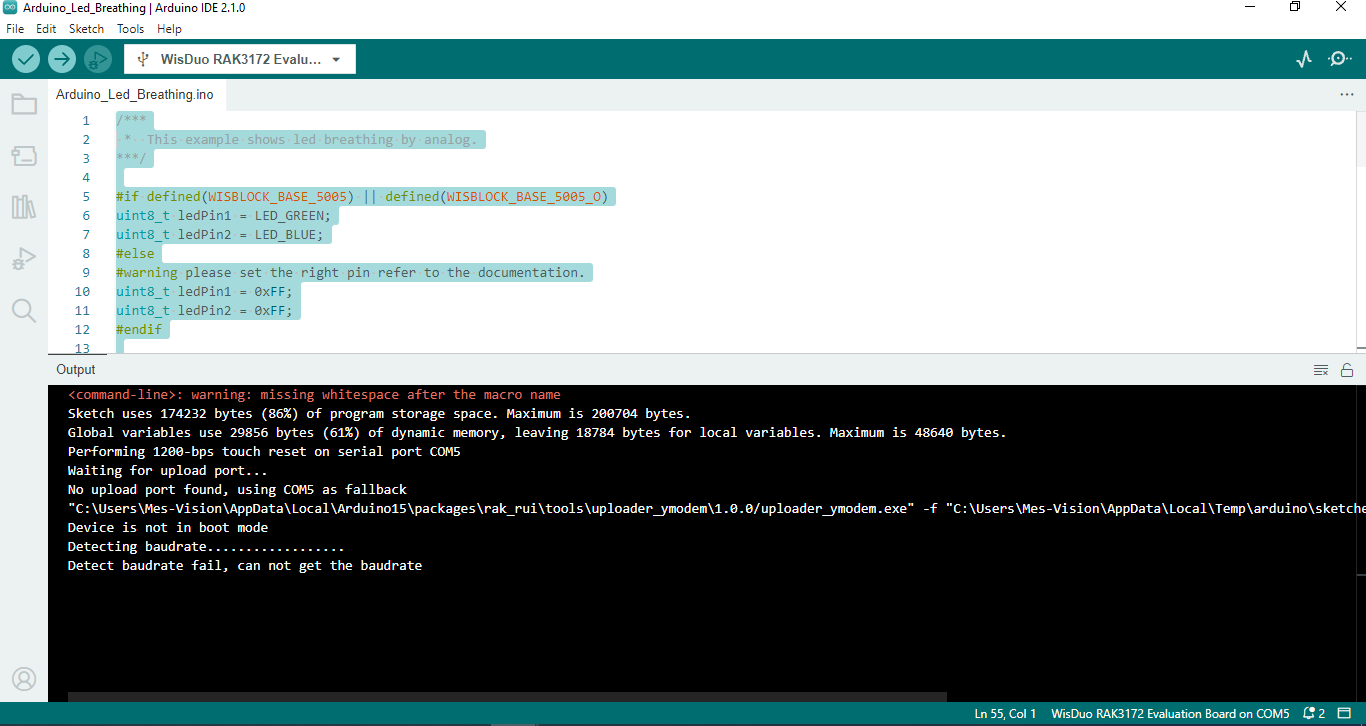
#warning please set the right pin refer to the documentation.
uint8_t ledPin1 = 0xFF;
uint8_t ledPin2 = 0xFF;
#endif
int val = 0; // variable for LED brightness value
bool state = false; // variable for control led brightness status
bool ledSwitch = false; // variable for switch led
void valChage()
{
state = !state;   // invert led control brightness status

if (val == 0)

    ledSwitch = !ledSwitch; // switch led when one of the led is darkest
}
void setup()
{
//initialize serial communcation at 115200 bits per second

Serial.begin(115200);

delay(2000);

Serial.println("RAKwireless Arduino LED Breathing Example");

Serial.println("------------------------------------------------------");

// initialize the LED pin as an output

pinMode(ledPin1, OUTPUT);

pinMode(ledPin2, OUTPUT);
}
void loop()
{
// call function when led is brightest or darkest

if (val == 0 || val == 255)

    valChage();

// determine to make the led lighter or darker

if (state)

    val++;

else

    val--;

// To switch the lighting led

if (ledSwitch)

    analogWrite(ledPin1, val);  // Light the green led

else

    analogWrite(ledPin2, val);  // Light the blue led
I have encountered a similar situation.
And there are many reasons for this error.
Most of them have the same problem that the RAK3172 has one or more pins that are communicating over 3.3V (maybe 4.2V or 5V…). So it’s broken.
In a document that I came across, I don’t remember which one it was.
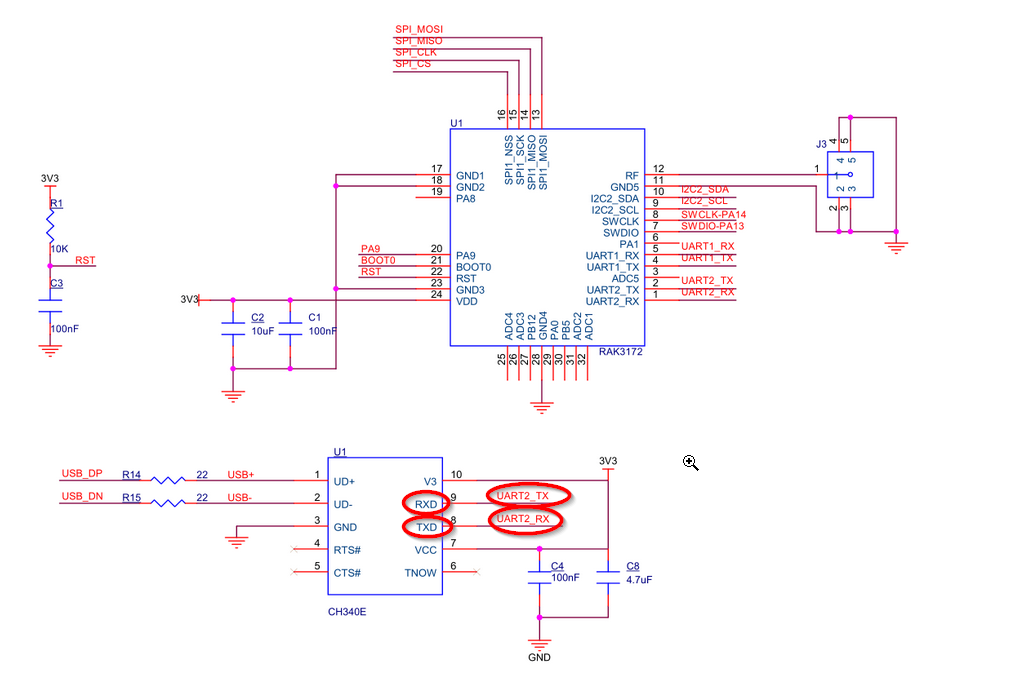
It mentions Tx2, and Rx2 can communicate with the outside via standard 5V.
But when I connected to CH340E with Vcc 5V I got an error can’t detect baud like the picture you provided.
Try the following steps before we get started with the more complicated stuff.
-Remove unnecessary connections to Tx2, Rx2.
-Check the connection of Tx2, Rx2. Make sure there is no open circuit.
-Power supply voltage at 3.3V
-Restart your laptop/PC
-Check Com port
Connecting to the same laptop/PC power outlet with interfering devices can also affect it. It is possible that an outdated adapter or an active inductive load is causing interference on the AC power system power line.
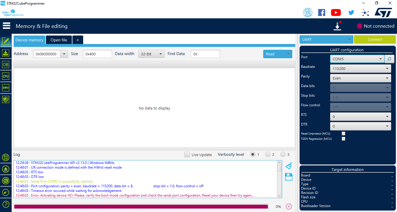
If you have my problem I think you can re-upload the code running the command AT+BOOT through serial just after the device is power up and before it goes dead.
The other solution of course would be to erase and upload a the latest .hex firmware with the ST-Link but you would need that tool first.
Anyway from what I can see when you don’t start the Serial or simply have somethings that gets stuck in the firmware you won’t be able to communicate with the RAK3172.
Thank you for reply me …
can you pls guide me to erase and upload .hex file
can you pls provide me .hex file and also connection diagram of ST-Link and RAK3172.