I was working on a SD Card example from NRF SDK v16 and was wondering about the SPI interface pin mapping. The example is using the following pin configuration :
In this approach, I see a problem with the clock pin, it’s not mapped to any port/pin on nrf52840.
Is the approach correct ? How can I properly map the clock pin ?
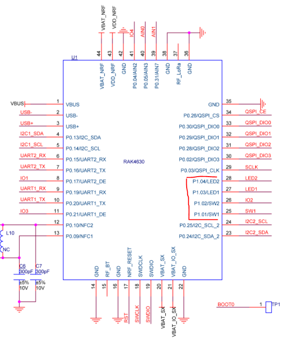
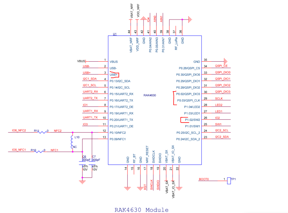
If you want to use SPI with WisBlock RAK4631 Core module, RAK5005-O Base Board and any WisBlock module that uses SPI you cannot change the assignment of the SPI pins.
You have to use what is assigned in variant.h of the Arduino BSP
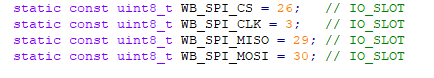
#define PIN_SPI_MISO (29) // => Port 1.13
#define PIN_SPI_MOSI (30) // => Port 1.14
#define PIN_SPI_SCK (3) // Port 0.03
    static const uint8_t SS = 26; // Port 1.10
If you change these, the connection of the SPI pins on the WisBlock modules will not work.
This is independent of using Arduino BSP or Nordic SDK. These connections are hardwired and you have to use exactly these assignments.
Right.
Can you explain how did you come up with the correct port/pin number on nrf52840 corresponding to the RAK4631 pins. For instance, how MISO Pin (29) is mapped on the port 1.13 ? Because I don’t see anything as such on the schematics or in variant.h