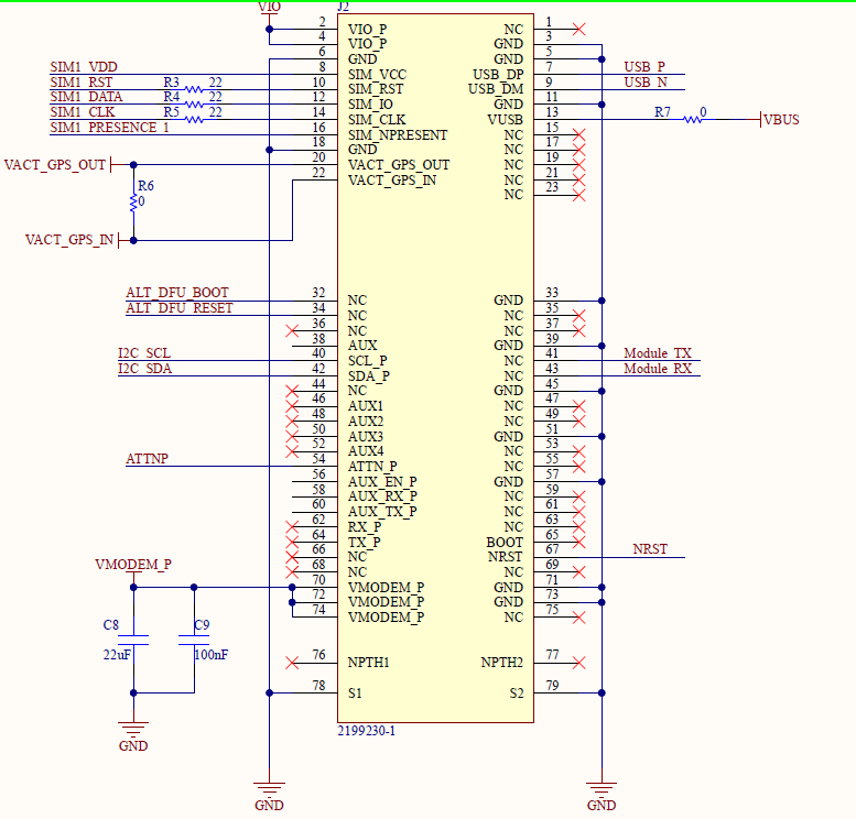
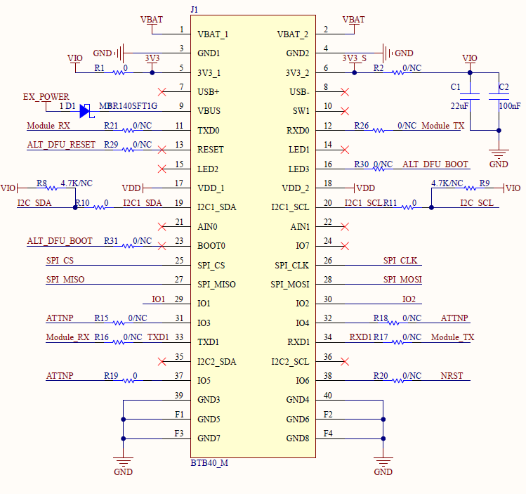
On the connector diagram you see 0/NC resistors on these lines.
That means there are resistors, but they are not assembled, so the lines are not connected.
You will have to place 0 Ohm resistors or solder bridges there to connect the lines.
Thanks for the quick response. Why would they not be connected?! Are there any technical implications for doing as you suggest? i.e. interfering with other components on the base? It feels like a lot of functionality to lose for the sake of a few resistors! Would be helpful to understand the rationale
It’s not about the resistors.
There was no working example from Blues about firmware updates of the host MCU through the Blues Notecard when the module was launched.
It didn’t make sense to connect something that limits the number of GPIO’s and UART available with nothing to use it.