I’m using a RAK 4631 module with a MQ2 gas sensor mounted to it. I am trying to use Lora P2P to send data to a T-Beam. Initially, I tried to use the SX126x-RAK4630 library to send data but I can’t seem to get it to work so I am trying to use the LoRa library by Sandeep mistry since it seems to be less complicated to me.
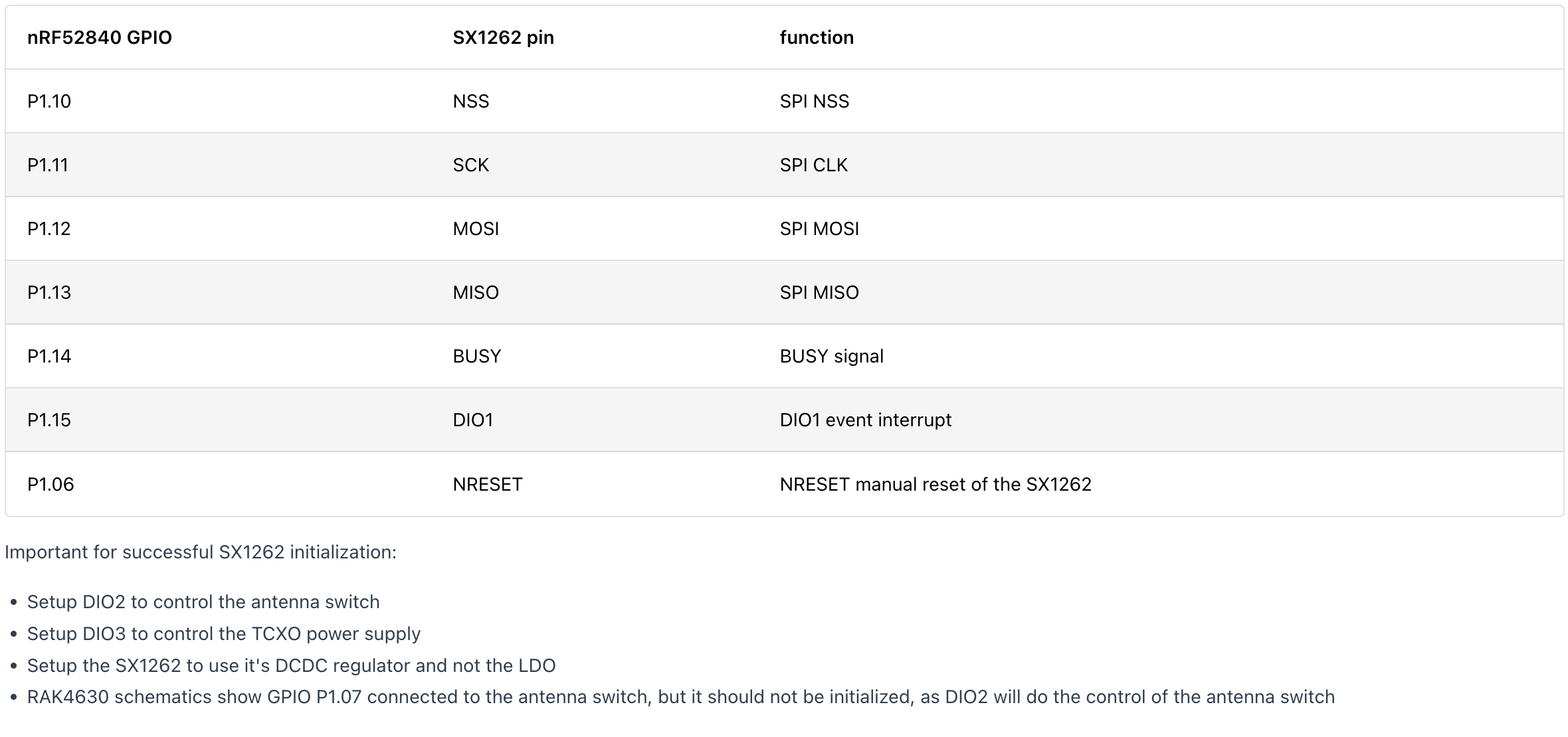
However, I can’t seem to understand the pin assignment for the LoRa in the RAK 4631. In the website they do mention the following but it is not clear enough which pin goes to which pin. Can someone explain the pin assignment since it seems there are 4 DIOx pins in RAK compared to the esp32 which has only 1. Attached below is the pin example on the website,
|P1.10|NSS|SPI NSS|
|P1.11|SCK|SPI CLK|
|P1.12|MOSI|SPI MOSI|
|P1.13|MISO|SPI MISO|
|P1.14|BUSY|BUSY signal|
|P1.15|DIO1|DIO1 event interrupt|
|P1.06|NRESET|NRESET manual reset of the SX1262|
In my arduino code, I am trying to define the pins in this way similar to the esp32
define SCK #define MISO #define MOSI #define SS #define RST #define DI0 #define BAND 923E6
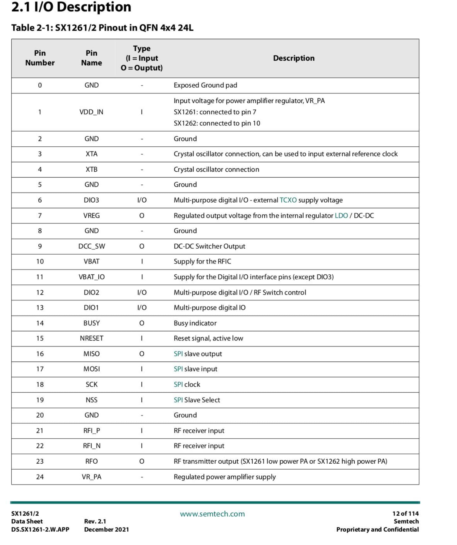
If you mean the arduino-LoRa library, that library is not working with the RAK4631. The RAK4631 is using the Semtech SX1262 transceiver. Sandeepemstry’s library is only supporting the older Semtech SX1276/77/78/79 transceivers.
Jgromes RadioLib is supporting the Semtech SX1262 transceiver.
According to him, this library allows us to establish connection between SX 126x LoRa module and SX 127x (T-Beam). However, the problem I face is I don’t understand the pin diagram and schematic of the RAK 4631 to enter to the code.
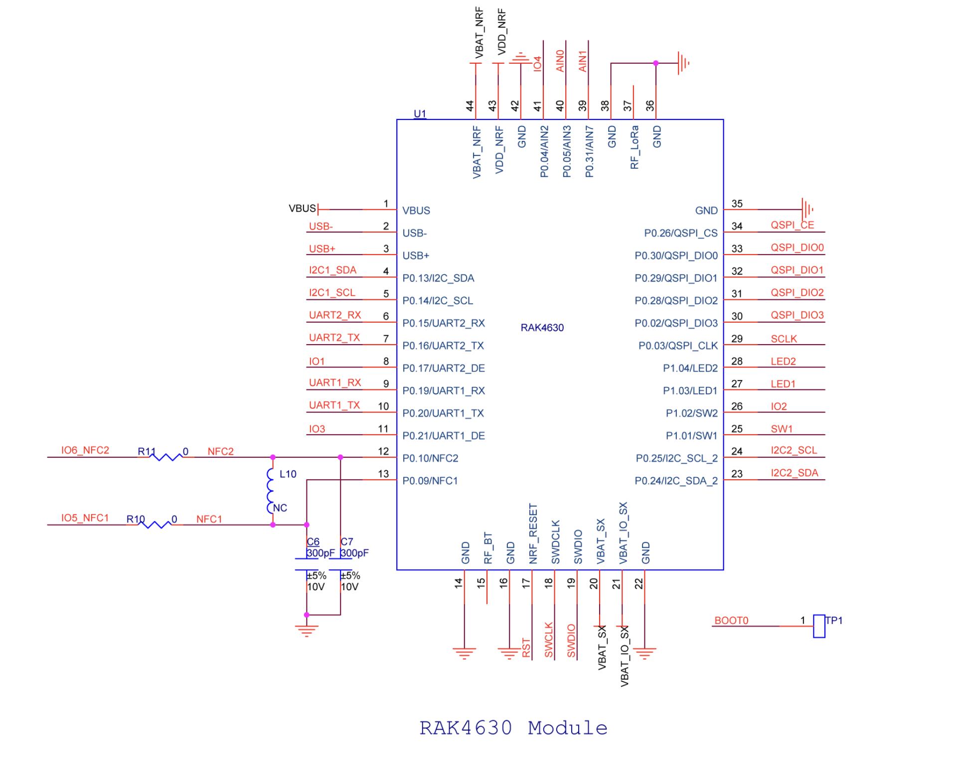
From the website, they have mentioned the pins for SX1262 as P1.10 which I don’t understand. I look at the schematic diagram and there isn’t a port number nor something marked as P1.10. If I could get help with that, it would be much appreciated thank you.
That is because the SX1262 transceiver is on the RAK4631 and directly connected to the nRF52840 through the pins listed in documentation.
These connection are not accessible on the pads of the RAK4630.
And SPI pin assignment is not the only thing that needs to be setup correct:
The RF switch is controlled by GPIO 37 (power on/off).
SX1262 must be setup to use DIO2 as RF switch control (RX/TX)
SX1262 must be setup to use DIO3 to switch on/off its TCXO
I see. Thank you @beegee . I want to know where I can find this information because to be honest I still cannot find this information anywhere.
And one more thing, regarding the pin assignments for the RF control and TCXO. Would defining them like this be fine? #define DIO2 37 #define DIO3 39
I do apologize since the pin mapping from nRF52 to Arduino is quite confusing to me.
The SX126x-Arduino Library looks good but the Read Me has not mentioned of support for the SX-127x. Since I’m trying to send LoRa signals to a T-Beam,I’m stuck in a little bit of a dilemma here. The library I am using that is, GitHub - StuartsProjects/SX12XX-LoRa: Library for SX12XX LoRa devices , is said to support this communication but it was designed based on an Atmel processor and there isn’t any mention of the DIO2, DIO3 pins here in the program.
You can use different libraries for different devices and as long as the P2P parameters are the same on both sides they can communicate. You do not need to use the same library on the RAK4631 and on your T-Beam.
I used the library mentioned below, earlier for the matter yet the T-Beam didn’t receive the signals which is what led me to use similar libaries. Is this library used for LoRa p2p between RAK modules only?
Hi @beegee , these are the 2 configurations for both my LoRa p2p programs. The receiving T-Beam doesn’t detect anything for some reason. Is it because of the parameters or the library?
I have used the same program as mentioned in the library and only added a 15 second delay to the end of the send(); loop to allow time for the T-Beam to detect it.
Below are the parameters and pin definitions for the T-Beam (SX1278) that is using LoRa library of sandeep mistry.
#include <SPI.h>
#include <Wire.h>
#include <Adafruit_GFX.h>
#include <LoRa.h>
//#include "Adafruit_SSD1306.h"

//defining the parameters for the lora peer to peer communication
#define SCK     5    // GPIO5  -- SX1278's SCK
#define MISO    19   // GPIO19 -- SX1278's MISO
#define MOSI    27   // GPIO27 -- SX1278's MOSI
#define SS      18   // GPIO18 -- SX1278's CS
#define RST     23   // GPIO14 -- SX1278's RESET
#define DI0     26   // GPIO26 -- SX1278's IRQ(Interrupt Request)
#define BAND    923E6
void setup()
{
	//pinMode(16, INPUT);
	//digitalWrite(16, LOW);
	//delay(50);
  //digitalWrite(16, HIGH);
	Serial.begin(115200);
	while (!Serial)
	{
		delay(100); //delaying for 100 milliseconds indefinitely
	}
  //Wire.begin(OLED_SDA, OLED_SCL);
  // if(!display.begin(SSD1306_SWITCHCAPVCC, 0x3c, false, false)){
  //   Serial.println("SSD1306 allocation failed");
  // }
	//***ADC121C021 ADC convert init ***********
	Serial.println("Lora Receiver Callback");
  SPI.begin(SCK,MISO,MOSI,DI0);
  LoRa.setPins(SS,RST,DI0);
  LoRa.setSpreadingFactor(7);
  LoRa.setSignalBandwidth(125000);
  LoRa.setCodingRate4(5);
  LoRa.setPreambleLength(8);
  if(!LoRa.begin(BAND)){
    Serial.println("Starting Lora failed!");
    while(1);
  }
  //Lora signal has been received
  Serial.println("init ok");
  //display.begin();
  //display.flipScreenVertically();
  delay(1500);
}
void loop()
{
  LoRa.receive(50000);
	int packetSize = LoRa.parsePacket();
  Serial.printf("The tbeam has entered the loop cycle\n");
  if (packetSize) {
    //received a packet
    //read packet
    while(LoRa.available()){
      LoraData = LoRa.readString();
      Serial.print(LoraData);
    }
    //print rssi of packet
    int rssi = LoRa.packetRssi();
    Serial.println(" with RSSI");
    Serial.println(rssi);
  }
  delay(30000);
}
Here I have added a 30 second delay between the loops too for the receiver. To my knowledge, I have set up the definitions correctly but nothing seems to work.
Thanks
If you have setup both devices with the same P2P parameters for frequency, bandwidth, spreading factor, coding rate, preamble length and syncword (should be the same by default) setup up one device to listen all the time and the other device to send only and test if it works.
Then switch the roles and test again.