Will the base board then be powered through the I/O port?
Or do I need an additional power-slot-module and “bridge” the +5V power from the 19018 to input of the power-slot module?
Asking because I had no success at the first attempt. Connected a PoE-enabled LAN cable, but the base board and modules showed no signs of life. Working on meshtastic, btw.
You will need an additional cable from the 5V output of the PoE board to the solar connector of the WisBlock Base Board to power the complete WisBlock setup through PoE.
If you need ethernet connectivity, RAK13800+RAK19018 is what you need then you can use the standard RAK19007 WisBlock Base board to eliminate the need for extra cable since the 5V output of the RAK19018 POE will be provided (ORed) in the VBUS line. On you current RAK19010 Base Board, the VUSB is not connected to the RAK19018 POE output so you will need the Solar cable.
I can enable POE on my WisBlock Base boards (RAK5005-O and RAK19007 boards) without the need of the cable connected to solar connector input.
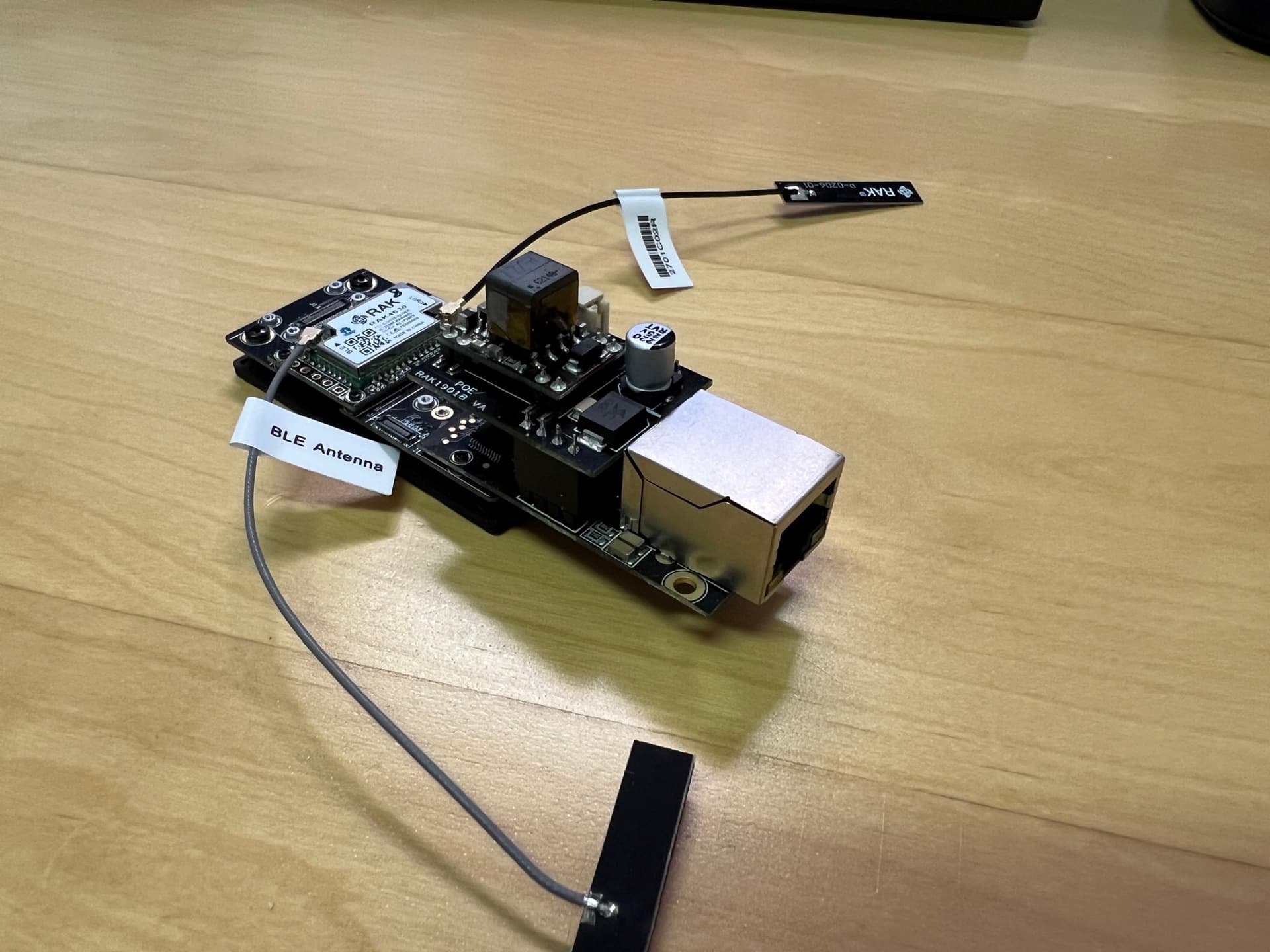
I’ve got a similar question, using the RAK19007 base board, and the RAK13800 Ethernet module with RAK19018 PoE board, when connecting a Ethernet cable from a PoE switch, only the red LED on the base board flickers a little dim, and the PoE module slightly buzzes, but the board does not start up.
It’s like it’s trying to start, but does not have enough power so it’s like stuck in a loop. What can I try?
Same issue here. And i’ve heard it mentioned similarly in a Mesthastic how-to build video featuring the wisblock and this PoE module. In the video the author mentions he tried a couple PoE switches before finding one that finally worked. He also found an injector that worked with the RAK 19018 module too.
But that begs the question, what determines whether a PoE injector/switch is “compatible” with the RAK 19018 board?
I have an open support ticket with RAK on this.
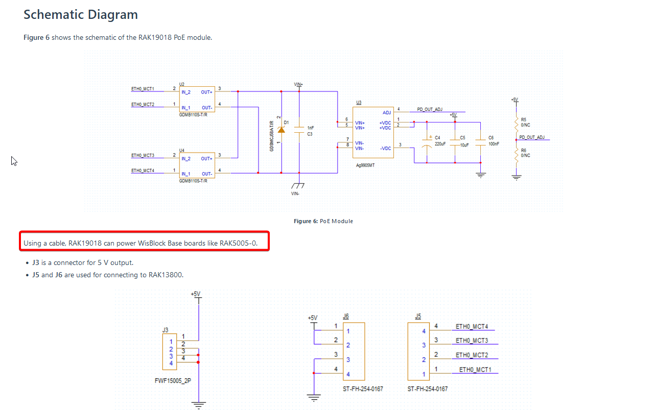
So far we’ve confirmed that the RAK 19018 is pushing 5v output on J6 (the connector used to power the wisblock base board), but only for a second. It shows 5.01v for about 1 second before gradually falling to 0.5v over the next 2 seconds. Then it goes back to 5.01v for 1 second and falls off again, repeats over and over again.
Its almost as if the PoE switch is trying to detect an expected resistance signature from the RAK 19018 and isn’t finding one so it just continually cycles.
It would seem there are PoE switches and injectors that implement a “passive” form of the 802.3af PoE standard and dont try to detect the consuming device, they just shove power. Maybe those are the devices that work with the RAK19018. I’m not sure yet.
I would expect if a module is advertised as a PoE device that it would work with the published 802.3af standard… so this is either an oversight on the RAK19018 design, or a batch of boards were built with a defect.
I am not exactly sure what you mean with solar cable. Would your setup have two power source? Solar and PoE? Both should be able to charge the battery. It is however critical to check the PoE output since it will pass thru two diodes before it reach the charging IC.
I do not experienced yet this intermittent on-off behavior on RAK13800+RAK19018.
However, one consideration is the minimum load required on the PoE board inside the RAK19018. You can probably try to add a Li-Ion battery on it to have a load. This will avoid the module to operate discontinuous mode. Also adding dummy resistor is also an option. This case is not seen on all users though.
If nothing works, we can continue our discussion on your current email support for possible replacement.
Here’s an explanation from our PoE module vendor with regards to discontinuous mode of operation.
If I power my modules via the RAK19007 board and USB-C, the modules work fine, Ethernet works too.
But if I mount the PoE module on top of the ethernet module and try to power it, the PoE module buzzes, and the power led on the base board only flashes shortly a second, and the process repeats, like @rkneeshaw mentions.
Carl, great find on that doc. That seems to explain what is happening here.
So it would seem the way to fix this is to add a battery or a resister. One would keep the board powered during power fluctuations, the other would add the artificial load to keep the module from going into discontinuous mode (technically, it would prevent minimum load from occuring causing the PSE to drop power to the port).
Do you have more advice where this dummy resister would be installed, and what ohm rating we should use? Would this be soldered somewhere on the base board?
For me it might sound easier to add a battery, I need to do some research but seems like that would be plug-and-play with the right parts…? My application needs to survive cold winter temperatures so I need to find the right battery solution.
Doing more research on this. Cold weather has me thinking the battery idea might not be the best.
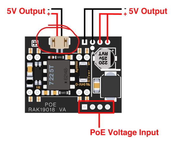
Regarding the resister idea. Would I just connect a resister in line between the + and - 5v output connector on the RAK19018 board? Would that create a steady load on the 19018 to keep it from going into the discontinous mode?
If we follow the requirements it should be 25ohms to achieve the 200mA load. However, this will have a continuous load of 1W. In addition, we do not consider yet the load of the other parts connected like the core, sensors, etc.
Probbly you can start on 100ohms and see if the sourcing equipment will be able to supply the PoE continuously. This can be a good compromise.
Thanks Carl. Trying to figure out what kind of connector that is for the 5v output on the RAK19018. I found reference to the connector part number, but having trouble finding a pigtail using that part number. Is there a common name for the connector I need to buy to plug into that 5v output? Without it I’m not sure where I’m going to solder in a resister.
Alternatively, would it be possible one of the Wisblock sensor boards would draw enough power to fix this? Maybe I just add a temperature sensor or a barometric pressure sensor? Could those possibly add enough load to maintain power signature?
Doing more research. Looks like most guys building a meshtastic setup on the Wisblock boards with a GPS module are seeing at most 50mA of current draw. Without GPS they see something like 2-5mA of current draw. That is so far below the 125mA or even 200mA required to prevent the RAK19018 PoE module from entering its non-continuous gated pulse mode.
I can’t see how adding any combination of add-on boards would get us to the current required to fix this issue. Only possible solution with this RAK19018 is going to be finding a way to solder in a resister somewhere, somehow, or finding a PoE power injector that isn’t smart enough to try to detect if the PoE device is or isn’t connected and just blindly shoves power.
The 5V connector for the PoE is compatible to the solar charger of the WisBlock Base board. Maybe this is an option where you can attach the dummy/load resistor. Of course directly soldering it on the 5V terminal pins is also possible.