Doing more research on this. Cold weather has me thinking the battery idea might not be the best.
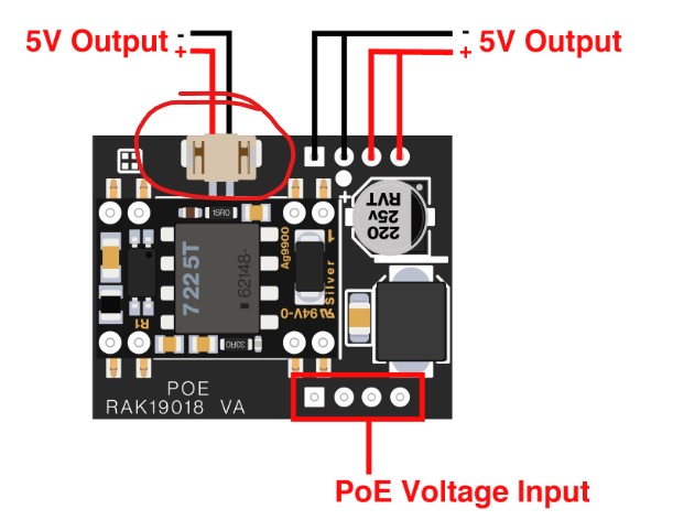
Regarding the resister idea. Would I just connect a resister in line between the + and - 5v output connector on the RAK19018 board? Would that create a steady load on the 19018 to keep it from going into the discontinous mode?
If we follow the requirements it should be 25ohms to achieve the 200mA load. However, this will have a continuous load of 1W. In addition, we do not consider yet the load of the other parts connected like the core, sensors, etc.
Probbly you can start on 100ohms and see if the sourcing equipment will be able to supply the PoE continuously. This can be a good compromise.
Thanks Carl. Trying to figure out what kind of connector that is for the 5v output on the RAK19018. I found reference to the connector part number, but having trouble finding a pigtail using that part number. Is there a common name for the connector I need to buy to plug into that 5v output? Without it I’m not sure where I’m going to solder in a resister.
Alternatively, would it be possible one of the Wisblock sensor boards would draw enough power to fix this? Maybe I just add a temperature sensor or a barometric pressure sensor? Could those possibly add enough load to maintain power signature?
Doing more research. Looks like most guys building a meshtastic setup on the Wisblock boards with a GPS module are seeing at most 50mA of current draw. Without GPS they see something like 2-5mA of current draw. That is so far below the 125mA or even 200mA required to prevent the RAK19018 PoE module from entering its non-continuous gated pulse mode.
I can’t see how adding any combination of add-on boards would get us to the current required to fix this issue. Only possible solution with this RAK19018 is going to be finding a way to solder in a resister somewhere, somehow, or finding a PoE power injector that isn’t smart enough to try to detect if the PoE device is or isn’t connected and just blindly shoves power.
The 5V connector for the PoE is compatible to the solar charger of the WisBlock Base board. Maybe this is an option where you can attach the dummy/load resistor. Of course directly soldering it on the 5V terminal pins is also possible.
I was trying to use this exact same setup for a Meshtastic gateway and I was also experiencing the same behaviour on a PoE switch–buzzing, pulsing LED, etc. I thought the RAK PoE hat was defective. I managed to get it working by using a cheap “dumb PoE injector” from aliexpress. I also tested a Ubiquiti PoE injector and that worked just as well. The smart PoE switches do not work on this RAK device!
I also have a bunch of the feather wing PoE ethernet boards, and those work great on a smart PoE switch, running a very low current MCU (particle xenon nrf52), so I know it’s possible to create a PoE hat that works as it should; and it’s up to RAK to make this product work properly (maybe hire Patrick, link below, to advise them on their circuit)
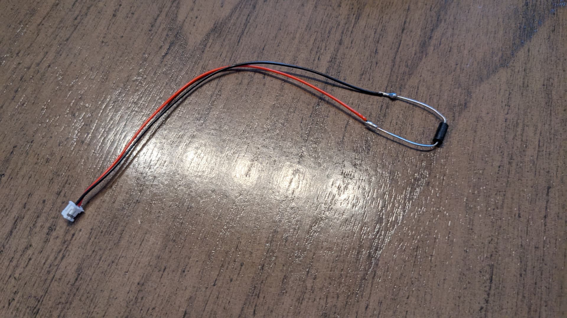
Confirmed! 25ohm resister did the trick. I didn’t test the 100ohm resister, since this is a PoE build, I’m not too worried about being perfectly efficient on the power draw, so the 25 ohm is fine for me.
I soldered the 25 ohm resister to the connector pigtail I found:
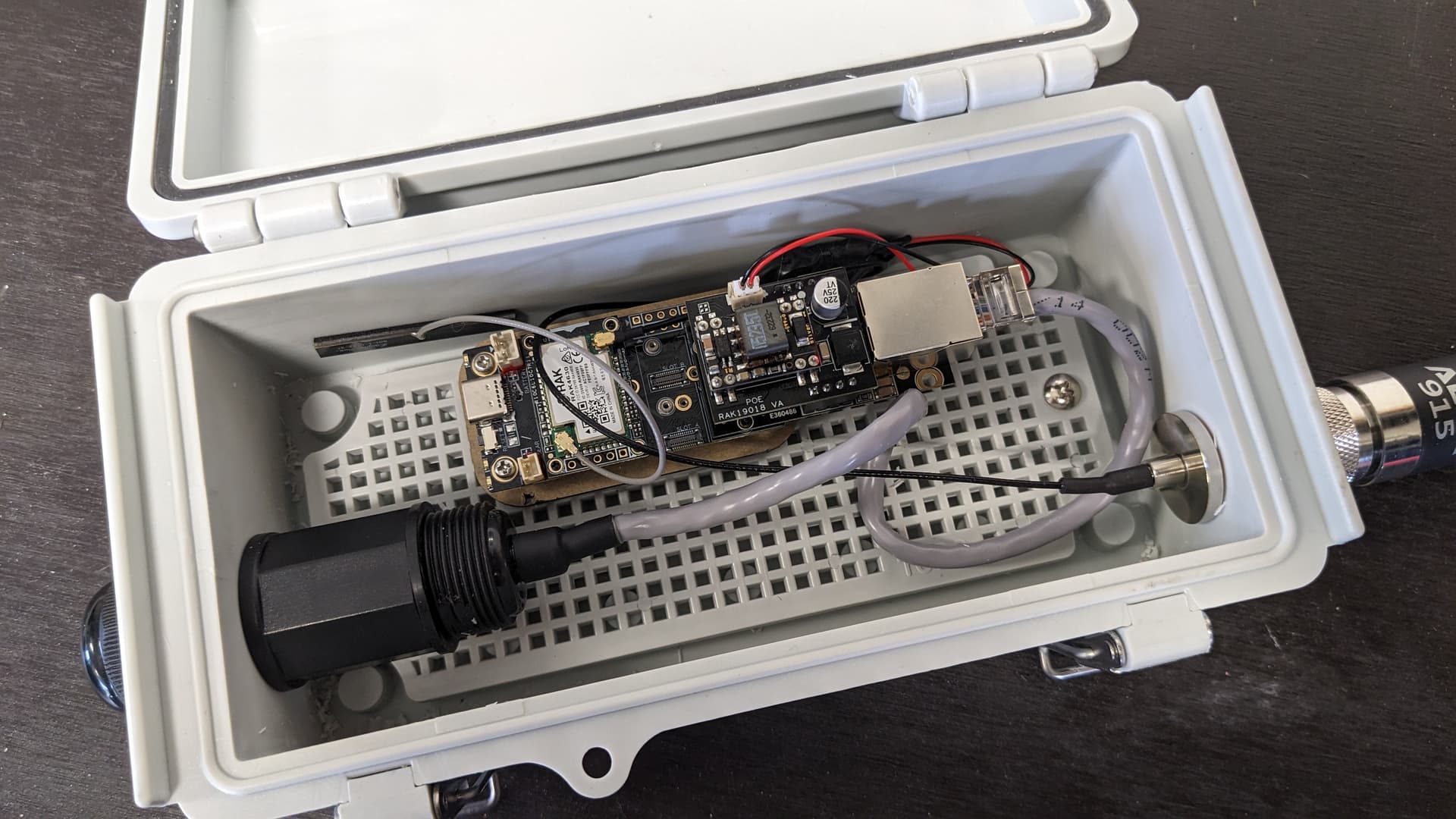
I connected the pigtail with 25 ohm resister to the 5v output of the RAK 19018 and this is the Final build with resistor leads taped up and tucked away:
Btw, I am not sure what is the power rating of your resistor but it will dissipate 1W continuously. Maybe at least 2W or even a bit bigger might better for long term outdoor deployment. Anyways, we can see its performance once out there
Great idea, I did use a 1w resister (not on purpose) and it gets a bit warm. I’m going to switch to a 2w or even a 5w is the same price, will give a little more headroom.
No problem to connect all three. battery will be charged through either PoE or solar (most likely through PoE, as it provides a stable 5V).
If PoE is down, powered by battery.
When using PoE with the RAK19018 module, several users recommend using “dumb” PoE injectors instead of smart ones, which can cause compatibility issues. Some also suggest adding a load resistor to improve power stability and prevent the module from misbehaving. Others found using a battery to provide a more consistent power source helpful
Hi Folks. I’ve got 19001 base board, 13800 ethernet module, and piggy back PoE module 19018.
The power pinout shown above and on the datasheet page below shows the incorrect polarity for the 5v outputs both on the header pins and the 2pin connector…
I verified this by checking the Poe module away from the main board on a meter and mounted to the base board. What’s shows as positive on the pinouts is directly connected to ground of the base board.
It appears to be a datasheet error and connecting actual 5v from the Poe header to the solar positive input works ok. No magic smoke.