
I’m reading the quick start guide and having a hard time wrapping my head around how to construct the message content. When looking at the example and the documentation i found online linked in this forum:
Since the example message starts with a colon, it seems it’s ASCII mode
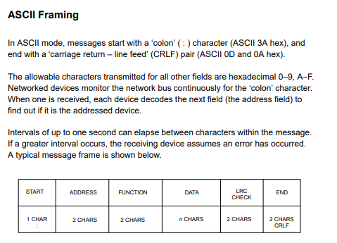
It seems that i need to calculate a Longitudinal Redundancy Check (LRC) for the message content also i need to add CRLF at the end.
Now looking at the examples in the quickstart:
- RS485 Temperature and humidity sensor addr: 01, Polling 1: 010300000002C40B
- RS485 Temperature and humidity sensor addr: 04, Polling 2: 040300000002C45E
- RS485 Temperature and humidity sensor addr: 08, Polling 3: 080300000002C492
- RS485 Temperature and humidity sensor addr: 0F, Polling 4: 0F0300000002C525
every single one has 02 as the LRC, and a random number instead of the CRLF.
Given the message 040300000002C45E
i would assume
5E would be the CRLF
C4 would the LRC
The actual message would be 040300000002, calculating the LRC on that yields 247 or F7, while in the example it is C4 / 196.
What am i missing here?