First of all great that you offer us a firmware with the core implementation to easily reach such a low power consumption during sleep, combined with the option to add our own “applications” !
The RAK5205 is a very nice board with great options. One thing I would like to do still is add an option to present some info to the user using up only very little power. To fulfill this requirement I am looking into using an a e-paper display. Most affordable (small) displays use a SPI interface. When looking at the new RUI API, SPI is however not supported on the 5205(RAK811). I am not an stm32 expert - so correct me if i’m wrong-, from what i understand however, the SPI 1 AFIO5 pins PB3,4,5 seem to be present on the IO pins of the RAK811H(868) module. For output only (spi write only), only PB3 and PB5 would be needed (PB4 has led connected). Is such a SPI option planned or can it be added as future API update for the RAK811 ?
Thank you!
For RAK811, there is only one SPI interface actually, and this SPI has been used for SX1276. That’s why we don’t supply SPI APIs.
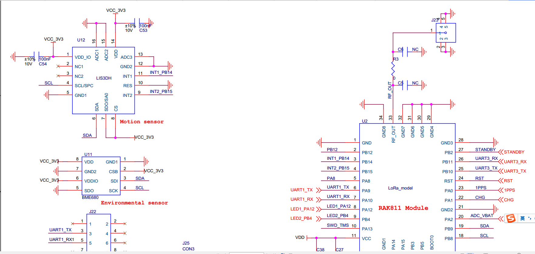
Yes, as you say, there are PIN 3, 4, 5 on RAK811 module, and we can use them to simulate a SPI interface. But on RAK5205, these pins has been used for LIS3DH sensor:
Surely, if you needn’t this sensor, we can remove it and we can use PIN 3, 4, 5 to simulate a SPI for your e-paper display.
But i still worry there may be some problem about timing sequence. We can think about it, and update a set of SPI APIs for this simulated SPI recently if it works well, if we can find a SPI sensor, we’ll do a product practice about this and update the source code on Github.
First of all thank you for your quick response. I am very pleased that RAK is open to and supportive of adding (simulated) SPI support to the 5205/RAK811.
To respond to your reply;
My remarks about in PB3,PB4 and PB5 may have been confusing; i was referring directly to the STM32 pins not the RAK811 pins. So on the RAK811, PIN 15= PB3, PIN 9= PB4 and PIN 16=PB5.
I would not recommend removing the I2C interface though, or replacing the sensor with a spi version, because on the I2C bus we can easily add more sensors without needing extra CPU pins, on SPI however we would need additional chip select pins if we add more devices.
I was under the impression that the RAK811 HIGH RF module, uses an STM32L151 CPU. From what i read in the datasheets they support 2 SPI interfaces. Can you confirm this ?
However to confirm your reply…
I found in the RAK811 schematic (https://github.com/RAKWireless/RAK811/blob/master/Hardware%20Design/RAK811%20SCH.pdf) that the lora module is connected to the SPI 1 interface.
This means that due to the configuration , if the STM32 would have a second hardware SPI this would/could theoretically be available on STM pins PB12,PB13,PB14,PB15. Because STM pin PB13 is used internally for the reset of the SX1276, and PB14 an PB15 are used for the LIS3DH interrupts there will be indeed no option to use the second HW SPI
So indeed it seems we are only left with the option of a software/bitbang SPI interface…maybe on PB3, PB5, PA8 and chips selects if needed through an I2C io expander…
I can have a look if i can get something to work for now with spi bitbang on these pins using the RUI GPIO Read/Write api…
Yes, STM32L151 MCU has 2 SPI interfaces, but one is used for SX1276 and the other hasn’t been pulled out on RAK811…
So the only selection option is to use simulated SPI.
As you see in the RAK5205’s schematic, there are 4 pins (PB3, PB5, PB12, and PA8) can be used if we don’t remove anything, and a simulated SPI need 4 IO interfaces. So i think that will be possible to do this using these 4 pins.
We’ll do some further development and test later.
That would be great !
The reason i mentioned only 3 pins, is that the CS pin was not included.
I would suggest though for the software SPI to have at least the option to leave the control of the CS pin to the developer.
This enables the developer to save an IO pin on the RAK811 and control the CS pin over an I2C IO expander.
Additionally for example an epaper display has a CS (chips select) but also a DC (data/control) line. If I run these two signals through an I2C expander then i can save two pins on the RAK811.
When only outputting data on the SPI bus, the MISO isnt needed either, if the MISO usage is also made optional it gives the developer also an extra IO.
So MOSI and CLK mandatory and CS and MISO optional would give the developer a lot of freedom to get the most out of the RAK811/5205 module
With the proposal above one may add a SPI epaper display using only 2 direct RAK811 pins running software SPI (MOSI/CLK) and an IO expander connected to the existing I2C (for CS and D/C), rather than using up to 5 RAK811 pins…