
HI .
How about everyone, I am doing a simple test using the RAk4631 where I turn on and off a 5V relay module every 30 seconds by IO1, the relay module is powered externally, when I feed the WB via USB the relay changes state every 30s, but when I feed through the solar connector, replacing the panel with a continuous source adjusted with 4V, it does not change the state correctly, even if I change the relay module for a led, when the datasheet indicates both have a connection behavior Similary.
The data sheet specifies which bus supports up to 5V, therefore in conn_s you can also have a continuous supply of 5V, right? However, I am concerned that if vbus and conn_s are similar I will get the error and the code will not be executed correctly feeding with 4V continuous in conn_s and with 5V in Vbus if you execute the code correctly.
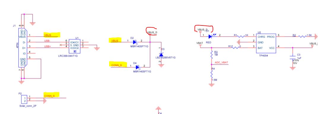
If you have USB connected VBUS should be 5V. If you feed 4V from CONN_S in addition, the diode D4 will block CONN_S.
If you have both USB and CONN_S supplying 5V the one with the slightly higher voltage will succeed. But I need to ask R&D if they tested it. But with normal deviations I guess one of the diodes will block even with same supply voltage on USB and CONN_S.
You say your relay is powered externally, so I guess you use IO1 to feed a transistor to turn on/off the relays contacts. Can you share the schematics how you did the connection/control?