Problem
Hello, I want to power my RAK board using a battery so that I can place it outside and collect UV-readings without having to connect the board to my Laptop. I need to do this for roughly an hour only.
Option 1
I have two 1.5V AA batteries that I can combine to produce 3V. These batteries have a current-voltage-time graph of:
(So if my board draws less than 100mA then the batteries should last at 1.5V for close to an hour).
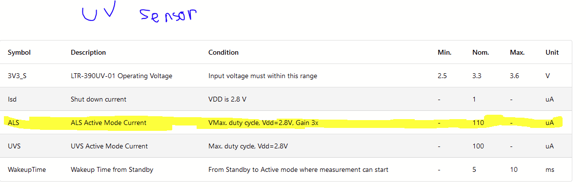
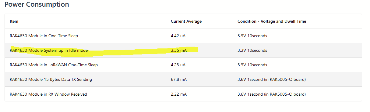
The RAK core only draws 3.35mA and the sensor only uses 110 microAmps so the batteries will be able to power the device. Also The RAK core operates on 2.0 - 3.6V and the sensor on 2.8V hence, the 3V should be enough.
Option 2
I have a 5V adapter (it has a very long cord which allows me to place my device outside). The adaptor has a current output of 500mA. I am worried that this current will destroy the RAK base.
Question 1
Can I connect my adaptor to the solar panel connector of the RAK base instead of the battery connector because the battery connector can only take 4.3V whilst the solar panel can take 5.5V.
Here is where I got the info from:
Question 2
Is it true that the RAK base regulates the amount of voltage and current that the RAK core and RAK sensor receives. i.e. if I supply 3.7V and 1A of power to the board and the sensor only needs 2.8V and 0.3A, will my board step down the voltage and current to 2.8V and 0.3A?
My equipment:
RAK core: RAK 4630
RAK base: RAK 5005-O
RAK sensor: RAK 12019 UV sensor
USB in (5V) and Solar in (3.7-5V) goes to the battery charger on the WisBlock Base Board.
The battery is (of course) on the charging output of the battery charger.
This output is connected to a 3.3V regulator which supplies the WisBlock Core and the WisBlock Sensor modules.
So the RAK4631 and the RAK12019 will always be supplied with 3.3V.
If you want to supply with non-rechargeable batteries, you should use at least 3 batteries to get 4.5V and supply over the solar panel connector. 3V is too less and the voltage regulator that is supposed to generate 3.3V will go into an undefined status and mostlikely draw a higher current than required.
I can confirm that I have had great success powering this device on the solar connector with 5V, that is a good route to take.
How you’re getting from 2-3V from your batteries to 5V at the input is very important for battery life, as the quiescent current of your boost converter could be multiple times that of the draw of your base + core + sensors. You should choose a high efficiency boost converter module for this task, perhaps something like this: High Efficiency Buck/Boost Converter Module from AstroSloth on Tindie
Cheaper modules from Amazon would do the trick as well for prototyping, but can often have idle current draws in the mA range, wasting your battery life away.