Hello, I have been using the 5-24V Power Module RAK19016 in several LoRaWAN industrial solutions, with the RAK19011 as the base, the RAK4631 as the core, a RAK15001 flash memory, and a RAK12034 module for motion monitoring.
The device operates with a 6V power supply and features a 3.7V SW18650 backup battery connected to the RAK19016.
The issue arises when the device switches from direct power to the backup battery. If the battery drops to the minimum required for data transmission and the transmission is interrupted, upon restoring the direct power supply, the node does not resume transmission but only charges the battery. Even if I disconnect the battery and keep only the power supply connected after the battery has been discharged, the device does not transmit.
The only way to make it transmit again is by disconnecting all power connections from the device.
This situation poses a significant problem for our industrial teams, as after long periods without power, the battery discharges, and upon power restoration, the device does not transmit automatically.
Hi @carlrowan have you listen about this? We have deployed +50 devices with this module, and we have confirmed this problem with the last 8 units. Have you experienced this?
Are you following the recommendation about Voltage and Current limits? If the discharge process is happening out of limits, you can damage the board and battery, for example the LiPo battery voltage need to operate between 3.0V and 4.2V, but the discharge should stop with 3.3V
HI @crmrosa I understand what the recommended voltages are for the operation of the device, only the problem is that if the power is available again, but the battery is already under the minimum voltage, the module does not work again.
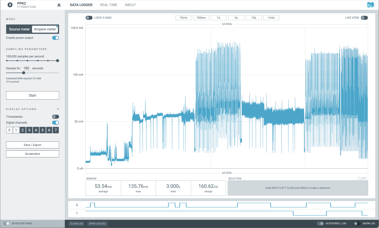
It is a excelent multimeter until 1A. It will help to measure how much your solution is consuming. You just need to connect it between your battery and your battery connector in the mother board and you will be able to monitor in your computer by USB port
Indeed, we have the Power Profiler Kit for testing, but the current incorrect behavior is that when the battery falls below the minimum threshold, the device turns off, which is expected. However, when external power is restored, the battery recharges but the device does not turn on, leaving the device non-functional even though the battery is charged and power is restored. Under this condition, we proceed to disconnect ALL power sources (battery and 12V) and enable them again, and at that moment the device turns back on.
This was replicated in the laboratory, having the same problem as in the field.
We have seen this behaviour before.
When the battery is complete empty and you start recharging the current the battery can supply is still very low.
When you start functions (like sending LoRa packets or starting up high power consuming sensors), while the battery is still weak, the voltage drops and the nRF52 detects a supply problem and shuts down.
Only way to get the nRF52 back is usually a power cycle or a reset. However, if at that point the battery is still weak, it goes into that status again.
Something I added in my code to avoid such situations is to check battery voltage as soon as possible when the device starts and if the battery voltage is very low, just do not anything for 10 minutes, then reset and try again.
/** Millivolts per LSB 3.0V ADC range and 12-bit ADC resolution = 3000mV/4096 */
#define VBAT_MV_PER_LSB (0.73242188F)
/** Compensation factor for the VBAT divider */
#define VBAT_DIVIDER_COMP (1.73)

void init_batt(void)
{
	// Set the analog reference to 3.0V (default = 3.6V)
	analogReference(AR_INTERNAL_3_0);

	// Set the resolution to 12-bit (0..4095)
	analogReadResolution(12); // Can be 8, 10, 12 or 14

	// Set the sampling time to 10us
	analogSampleTime(10);
}

float read_batt(void)
{
	float raw;

	// Get the raw 12-bit, 0..3000mV ADC value
	raw = analogRead(vbat_pin);

	// Convert the raw value to compensated mv, taking the resistor-
	// divider into account (providing the actual LIPO voltage)
	// ADC range is 0..3000mV and resolution is 12-bit (0..4095)
	return raw * REAL_VBAT_MV_PER_LSB;
}

void setup(void)
{
	// Make sure 3V3_S and the LED's are off
	pinMode(WB_IO2, OUTPUT);
	pinMode(LED_GREEN, OUTPUT);
	pinMode(LED_BLUE, OUTPUT);
	digitalWrite(WB_IO2, LOW);
	digitalWrite(LED_GREEN, LOW);
	digitalWrite(LED_BLUE, LOW);

	// Check battery level
	init_batt();
	float batt_level_f = read_batt();
	for (int idx = 0; idx < 10; idx++)
	{
		batt_level_f += read_batt();
	}
	batt_level_f = batt_level_f / 10.0;

	if (batt_level_f < 3700.0)
	{
		// Battery below 3.7V, try to initialize the LoRa transceiver
		lora_rak4630_init();
		// Set LoRa transceiver to sleep
		Radio.Sleep();
		// Sleep for 10 minutes
		delay(600000);
		// Reset device and try again
		sd_nvic_SystemReset();
		// api_reset();
	}
}
Okay, I understand what you’re trying to get at, the problem is that when the main power is restored, the battery starts charging, and even though the main battery returns to 4.2V, the device doesn’t start transmitting again.
Anyway, I’m trying to use the solution you gave me. In my code, I have the following error:
src\main.cpp: In function ‘void setup()’:
src\main.cpp:78:3: error: ‘sd_nvic_SystemReset’ was not declared in this scope
sd_nvic_SystemReset();