If you follow our Quick Start Guide you should be able to use the RAK12500.
There are two ways to reduce the power consumption of the RAK12500.
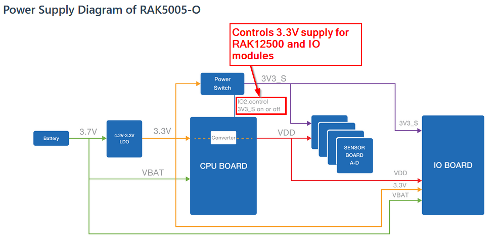
The power supply of the whole module can be controlled using WB_IO2 GPIO.
pinMode(WB_IO2, OUTPUT);
digitalWrite(WB_IO2, LOW); // Power off the whole module
digitalWrite(WB_IO2, HIGH); // Power on the whole module
Using the low power mode of the uBlox chip.
pinMode(WB_IO2, OUTPUT);
digitalWrite(WB_IO2, HIGH); // Power on the whole module
...
... // Initialize I2C and setup the uBlox chip
...
my_gnss.powerSaveMode(true); // Put uBlox chip into low power mode
I have tested both methods and 1) is better in power saving (obviously because you cut the power supply). 2) only works if the uBlox chip has already obtained a location fix. Otherwise it seems the chip (or the Sparkfun library, I don’t know) seems to ignore the command. But if the uBlox goes into power save mode, the consumption is reduced, but not as much as I expected. Sorry, I do not have the measurements anymore.
the negative thing with solution 1) is that after each power up the uBlox has to search again for satellites, which can take up to 1 minute, depending on how fast the chip can find satellites.
Thanks again my friend … though I am curious, since I’ve got a couple of LEDs wired to the RAK50005 board and they are using WB_IO1 and WB_IO2 … I am signalling the LED on WB_IO2 and yet the GPS board is not affected by this
What I’ve discovered today is that by having RAK12500 in slot A on the RAK5005-0 board, one cannot rely on the headers of J11.
A further observation has been that with the RAK12500 connected to slot A, reset button must be pressed after applying power, whether this is via USB or battery.
This can be demonstrated simply with the following sketch.
Attach an LED (and a resistor, I used a 1K) to IO1 (J11) and ground it to GND (J12) fire up the power either with a USB cable or with a 3.7V batttery, and you will see the onboard blue LED flash, after which, the attached LED will perform it’s cycle indefinitely.
Now disconnect the power and attach RAK12500 to slot A and again power up the board.
Try powering with both USB and the 3.7V battery: you will need to press the reset button to start the program running, and then you will only see the onboard blue LED flash, the attached LED will not work
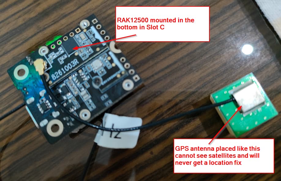
Further observation is that by moving the RAK12500 to the underside of the board and into slot C, the external LED can now be used as expected, however, we can no longer get a GPS fix!!!
Hello @billr
Trying to respond to all your posts one by one
Vbat is measured with WB_A0, not with WB_A1
reset button must be pressed ==> Did you upgrade the bootloader of your RAK4631? This is an old problem that was fixed in April 2021. See here: Updated Bootloader for RAK4631
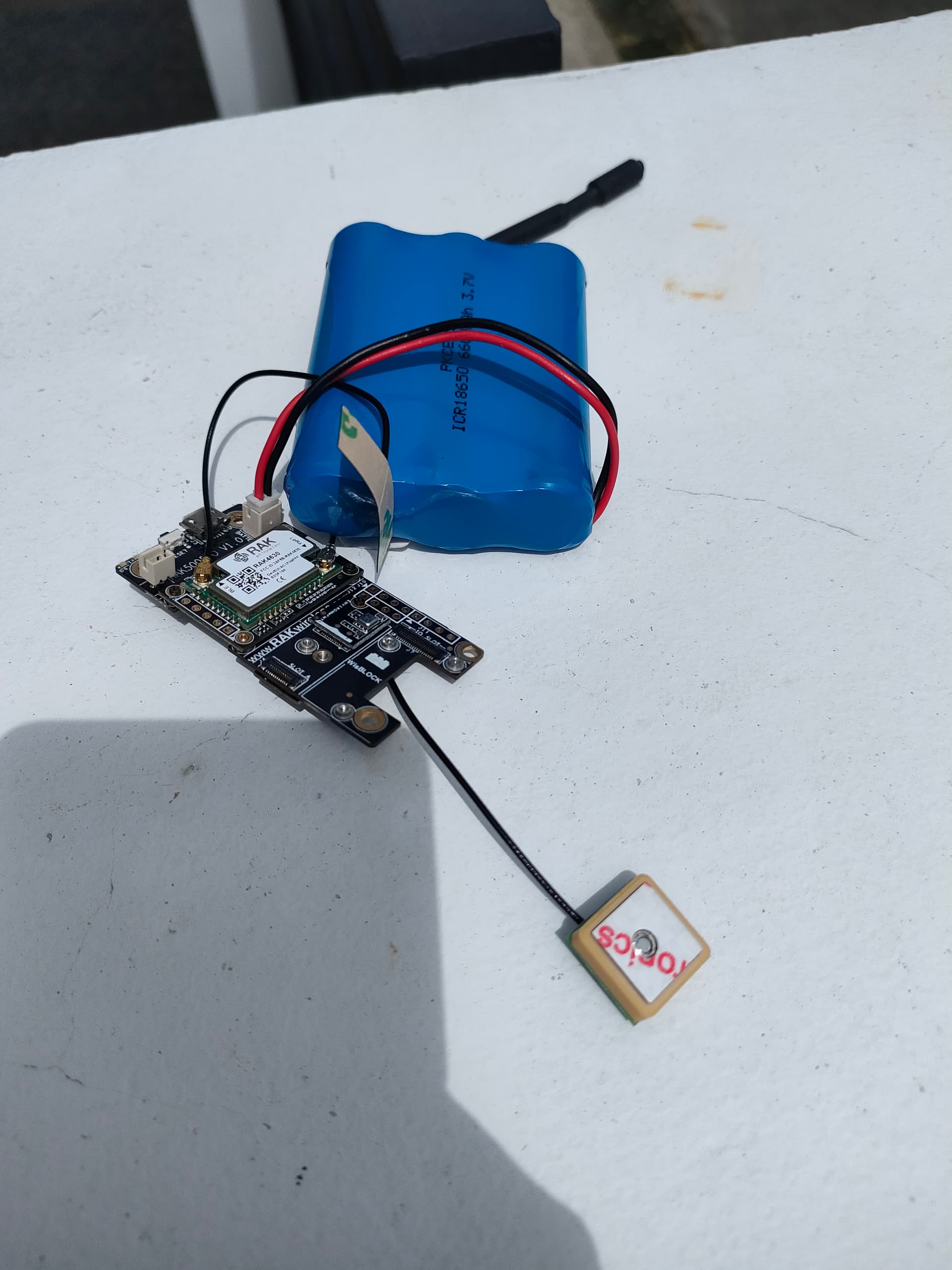
Using the RAK12500 in Slot C has no effect on finding a location as long as you make sure the GPS antenna is point to the sky in the correct orientation
Correct:
Btw, above pictures are taken from my private project to build a small GPS tracker. The Base board used here is not yet available, but will come within this year into our store.
It turns out that the bootloader is dated Jun 16 2020 … so I can think that I can safely say we do not have the updated bootloader.
I do find this curious though, since we have only purchased these boards recently (as in last month): I will have to check all of the boards we have to make sure they are all up to date in this respect.
I’m going to update at least one of them today and let you know how that goes.
With regards to VBAT:
#define PIN_VBAT WB_A0
#define PIN_SOLAR WB_A1
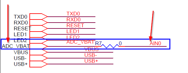
These are the pins we have defined (actually taken from one of the example sketches), however, I have found that AIN1 (from J11) is actually connected to WB_A0
I can assure you my friend that all of my observations reported are exactly the case.
If I place RAK12500 in slot A, I cannot use WB_IO1, however this is not the case at all if the RAK12500 is plugged in to slot C. Also, with RAK12500 connected in slot A, the GPS functionality works exactly as expected (SIV = 6,7,8 and 10), however with the connection instead to slot C, I have had the code running for over 12 hours and the GPS unit does not connect to more than 3 satellites, whilst most of the time SIV = 0
About J11, I apologize, I only looked on the Base board, not into the schematics. And the print on my base board is quite bad. You are right, on J11 it is AIN0.
WB_IO1 of Slot A is connected to the 1PPS pin of the uBlox. I forgot about that (It was a long week). That’s why you can’t use it.
My code is not reading the SIV, I am only looking into the fix type and I get a 3D fix whatever slot I use. As the GPS antenna is away from the module, I do not know what could cause the problem in your case. I will try to add SIV to my code and see what results I get
We are producing in batches of at least 5000 pcs, so it will take some time before the modules with the new bootloader will be send out. The bootloader is flashed during the production, and it would be a big effort and quality risk if we reprogram all modules that are still in stock. Sorry for the inconvenience.
It is really weird.
I changed my code a little bit to get the SIV value and I have no problems to get 9 satellites with the RAK12500 in Slot C.
As the slot connectors are identical (only the IO’s connected are different), that is the expected behavior.
Do you have several RAK5005-O Base boards to test with? Just to eliminate that it is caused by the Base board.
@beegee, so having discovered that the wiring that we “require” -i.e. using the GNSS chip and connecting a couple of LEDs- is not possible when using just the base board, we’ve decided to go with onboard LEDs until we can take delivery of some IO modules.
With regards to connection sockets… on one of the boards at least, when connecting the GPS to socket C, it cannot be found on the IIC bus, on another board we can get no higher than SIV=3. very peculiar.
Right now however, this is no longer an issue for us since we have decided to take the LEDs out of the equation (for the time being).
If you have time to test, on the RAK5005-O with the problem that RAK12500 cannot be found on I2C bus in slot C, can you test another module (any module with I2C bus) if it is detected?
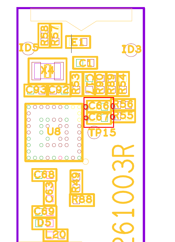
For the other module, where you cannot get more than SIV=3, can you test the voltage on the RAK12500. The 3.3V for the module can be measured on C66 or C67:
No other change was made and nothing was touched on the hardware. The program was uploaded to the board; and I am unable to find the GPS unit on the default I2C address … bear in mind that, I’ve not actually run a scan to see if I can find any I2C addresses, I am simply going on the fact that the call togpsUnit.Initialize()is failing.
I swapped the GPS unit over for another one … same deal, cannot find GPS unit. I then (simply out of curiosity) unplugged from slot A and plugged into slot C, powered up the board and everything works … this is the very board that (on saturday) could not locate the GPS unit when plugged in to slot C.
I then swapped the GPS unit back to port A, and still unable to initialize the unit.
NOTE
I recognise that gpsUnit.Initialize() doesn’t mean much to you, but it’s a wrapper function defined as follows
bool GpsUnit_t::Initialise()
{
    if (_gnss.begin() == false) //Connect to the u-blox module using Wire port
      return false;

    _gnss.setI2COutput(COM_TYPE_UBX);            //Set the I2C port to output UBX only (turn off NMEA noise)
    _gnss.setMeasurementRate(GNSS_DATA_RATE);    //Produce a measurement every second
    _gnss.setNavigationRate(1);                  //Produce a navigation solution every measurement
    _gnss.setAutoPVT(true);

    _gnss.setAutoPVTrate(1);                     //Tell the GNSS to send the PVT solution every measurement
    _gnss.setAutoNAVVELNEDrate(1);
    return true;
}
Just to make sure it’s not anything to do with the code, and I get the same deal: there really is no rhym or reason to it at all, sometimes it will work, sometimes it will not, however there is one consistency in that if the GPS unit is initialised and I subsequently disconnect the USB and then re-connect, it will cease to work!