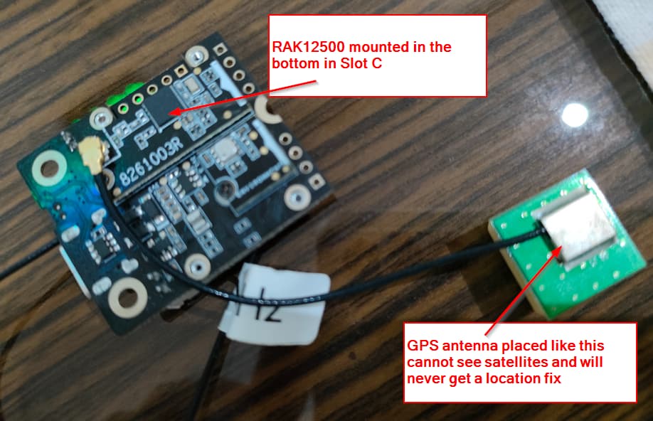
Further observation is that by moving the RAK12500 to the underside of the board and into slot C, the external LED can now be used as expected, however, we can no longer get a GPS fix!!!
Hello @billr
Trying to respond to all your posts one by one 
-
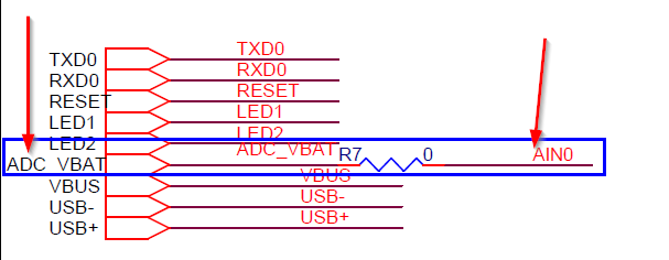
Vbat is measured with WB_A0, not with WB_A1
-
reset button must be pressed==> Did you upgrade the bootloader of your RAK4631? This is an old problem that was fixed in April 2021. See here: Updated Bootloader for RAK4631 -
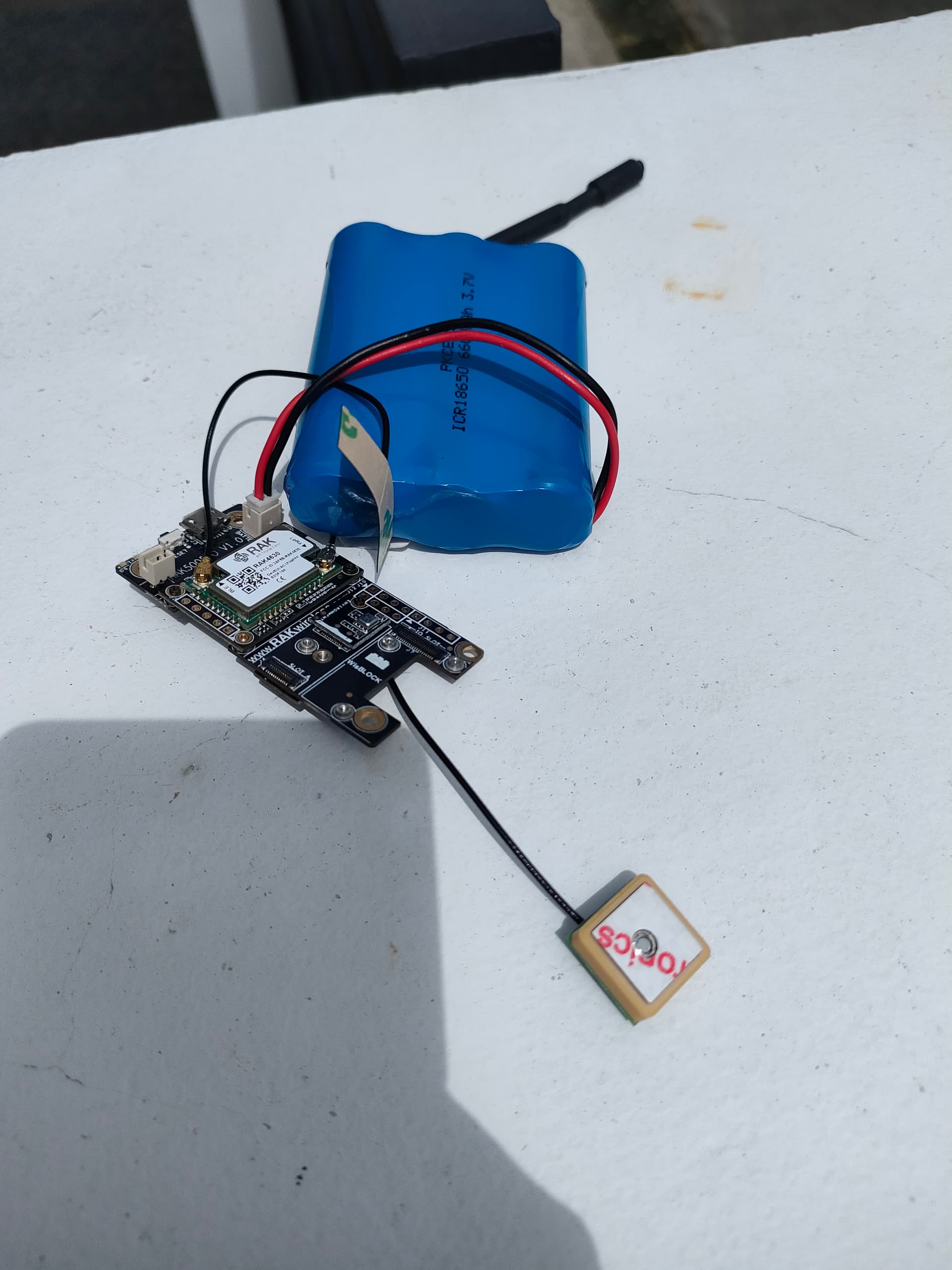
Using the RAK12500 in Slot C has no effect on finding a location as long as you make sure the GPS antenna is point to the sky in the correct orientation
Correct:
Wrong:

Btw, above pictures are taken from my private project to build a small GPS tracker. The Base board used here is not yet available, but will come within this year into our store.
It turns out that the bootloader is dated Jun 16 2020 … so I can think that I can safely say we do not have the updated bootloader.
I do find this curious though, since we have only purchased these boards recently (as in last month): I will have to check all of the boards we have to make sure they are all up to date in this respect.
I’m going to update at least one of them today and let you know how that goes.
With regards to VBAT:
#define PIN_VBAT WB_A0
#define PIN_SOLAR WB_A1
These are the pins we have defined (actually taken from one of the example sketches), however, I have found that AIN1 (from J11) is actually connected to WB_A0
I can assure you my friend that all of my observations reported are exactly the case.
If I place RAK12500 in slot A, I cannot use WB_IO1, however this is not the case at all if the RAK12500 is plugged in to slot C. Also, with RAK12500 connected in slot A, the GPS functionality works exactly as expected (SIV = 6,7,8 and 10), however with the connection instead to slot C, I have had the code running for over 12 hours and the GPS unit does not connect to more than 3 satellites, whilst most of the time SIV = 0
@beegee As expected, the bootloader has fixed the start-up issue.
It’s probably safe to say then that my hardware was manufactured earlier than the updated bootloader was published.
About J11, I apologize, I only looked on the Base board, not into the schematics. And the print on my base board is quite bad. You are right, on J11 it is AIN0.
WB_IO1 of Slot A is connected to the 1PPS pin of the uBlox. I forgot about that (It was a long week). That’s why you can’t use it.
My code is not reading the SIV, I am only looking into the fix type and I get a 3D fix whatever slot I use. As the GPS antenna is away from the module, I do not know what could cause the problem in your case. I will try to add SIV to my code and see what results I get
We are producing in batches of at least 5000 pcs, so it will take some time before the modules with the new bootloader will be send out. The bootloader is flashed during the production, and it would be a big effort and quality risk if we reprogram all modules that are still in stock. Sorry for the inconvenience.
1 Like
It is really weird.
I changed my code a little bit to get the SIV value and I have no problems to get 9 satellites with the RAK12500 in Slot C.
As the slot connectors are identical (only the IO’s connected are different), that is the expected behavior.
Do you have several RAK5005-O Base boards to test with? Just to eliminate that it is caused by the Base board.
Here my log and my setup:

@beegee, so having discovered that the wiring that we “require” -i.e. using the GNSS chip and connecting a couple of LEDs- is not possible when using just the base board, we’ve decided to go with onboard LEDs until we can take delivery of some IO modules.
With regards to connection sockets… on one of the boards at least, when connecting the GPS to socket C, it cannot be found on the IIC bus, on another board we can get no higher than SIV=3. very peculiar.
Right now however, this is no longer an issue for us since we have decided to take the LEDs out of the equation (for the time being).
If you have time to test, on the RAK5005-O with the problem that RAK12500 cannot be found on I2C bus in slot C, can you test another module (any module with I2C bus) if it is detected?
For the other module, where you cannot get more than SIV=3, can you test the voltage on the RAK12500. The 3.3V for the module can be measured on C66 or C67:
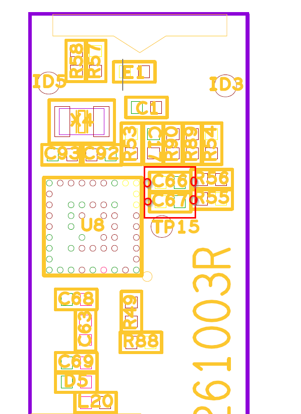
If there is a problem with the boards, we need to check and find the cause.
Thank you.
Here’s something very peculiar @beegee: I made the following code change
From this:
  if(!gpsUnit.Initialize())
  {
#ifdef CONNECTED_FOR_DEBUG
    Serial.println(F("u-blox GNSS not detected at default I2C address. Please check wiring. Freezing."));
#endif // CONNECTED_FOR_DEBUG
    while(1) { Serial.print("FAIL ");}
  }
to this:
  while(!gpsUnit.Initialize())
  {
#ifdef CONNECTED_FOR_DEBUG
    Serial.println(F("u-blox GNSS not detected at default I2C address. Please check wiring. Freezing."));
#endif // CONNECTED_FOR_DEBUG
    digitalToggle(SUCCESS_LED);
    digitalToggle(FAIL_LED);
    vTaskDelay(1000);
  }
No other change was made and nothing was touched on the hardware. The program was uploaded to the board; and I am unable to find the GPS unit on the default I2C address … bear in mind that, I’ve not actually run a scan to see if I can find any I2C addresses, I am simply going on the fact that the call to gpsUnit.Initialize() is failing.
I swapped the GPS unit over for another one … same deal, cannot find GPS unit. I then (simply out of curiosity) unplugged from slot A and plugged into slot C, powered up the board and everything works … this is the very board that (on saturday) could not locate the GPS unit when plugged in to slot C.
I then swapped the GPS unit back to port A, and still unable to initialize the unit.
NOTE
I recognise that gpsUnit.Initialize() doesn’t mean much to you, but it’s a wrapper function defined as follows
bool GpsUnit_t::Initialise()
{
    if (_gnss.begin() == false) //Connect to the u-blox module using Wire port
      return false;

    _gnss.setI2COutput(COM_TYPE_UBX);            //Set the I2C port to output UBX only (turn off NMEA noise)
    _gnss.setMeasurementRate(GNSS_DATA_RATE);    //Produce a measurement every second
    _gnss.setNavigationRate(1);                  //Produce a navigation solution every measurement
    _gnss.setAutoPVT(true);

    _gnss.setAutoPVTrate(1);                     //Tell the GNSS to send the PVT solution every measurement
    _gnss.setAutoNAVVELNEDrate(1);
    return true;
}
@beegee, I really do not know what is going on with the two boards I have here …
both of them are pretty random in deciding whether or not the GPS unit can be initialised.
One of them will not initialise at all now using slot A, and in slot C, sometimes it initialises, sometimes it does not.
The other board I can get to initialise when using slot A, but here’s the crazy routine I need to follow in order to get it to work:
- Connect to USB
- Unplug GPS unit from slot A
- Plug GPS unit back in to slot A
- Press the reset button
If Ishould unplug the USB cable and then re-insert it, again the GPS unit cannot be initialised!!
I’ve stripped my code down to the bare minimum
#include <Arduino.h>
#include <SparkFun_u-blox_GNSS_Arduino_Library.h>

SFE_UBLOX_GNSS _gnss;

void setup() {
  Wire.begin();
  vTaskDelay(10);
  while(!_gnss.begin())
  {
    digitalToggle(LED_BLUE);
    digitalToggle(LED_GREEN);
    vTaskDelay(1000);
  }
}

void loop() {
}
Just to make sure it’s not anything to do with the code, and I get the same deal: there really is no rhym or reason to it at all, sometimes it will work, sometimes it will not, however there is one consistency in that if the GPS unit is initialised and I subsequently disconnect the USB and then re-connect, it will cease to work!
Hi Bill,
The other board I can get to initialise when using slot A, but here’s the crazy routine I need to follow in order to get it to work:
Connect to USB
Unplug GPS unit from slot A
Plug GPS unit back in to slot A
Press the reset button
If Ishould unplug the USB cable and then re-insert it, again the GPS unit cannot be initialised!!
NEVER EVER PLUG-IN OR PLUG-OUT A WISBLOCK MODULE WHILE THE WISBLOCK BASE BOARD IS POWERED! OUR MODULES ARE NOT DESIGNED FOR HOT-PLUG
That said, if you plugged-in or plugged-out a module under power before, I cannot say if the WisBlock Base board or the GNSS module is damaged.
   digitalToggle(SUCCESS_LED);
    digitalToggle(FAIL_LED);
What are the GPIO numbers of SUCCESS_LED and FAIL_LED ?
Are you securing the modules with the screws after you plugged them in?
SUCCESS_LED = LED_BLUE
FAIL_LED = LED_GREEN
That said, if you plugged-in or plugged-out a module under power before, I cannot say if the WisBlock Base board or the GNSS module is damaged.
This happened by accident today after the board had stopped recognising the module (I had to take everything out of the enclosure we have built) and it certainly has only happened to that one board and that one GPS module
Hi Bill,
Accidents can happen, just wanted to make sure.
RAK engineers have tested RAK12500 in both slot A and C and I have tested it as well in both slots without problems.
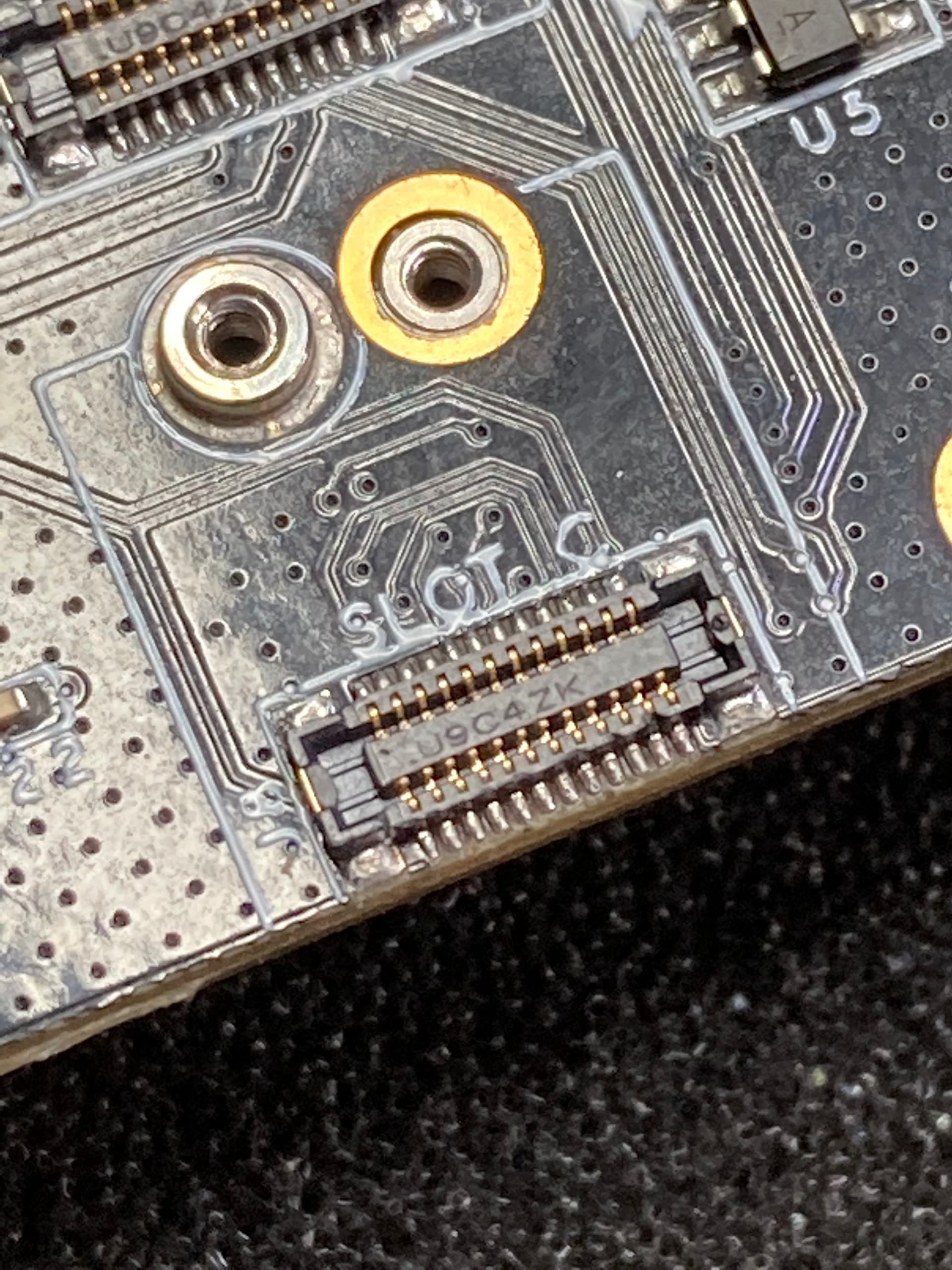
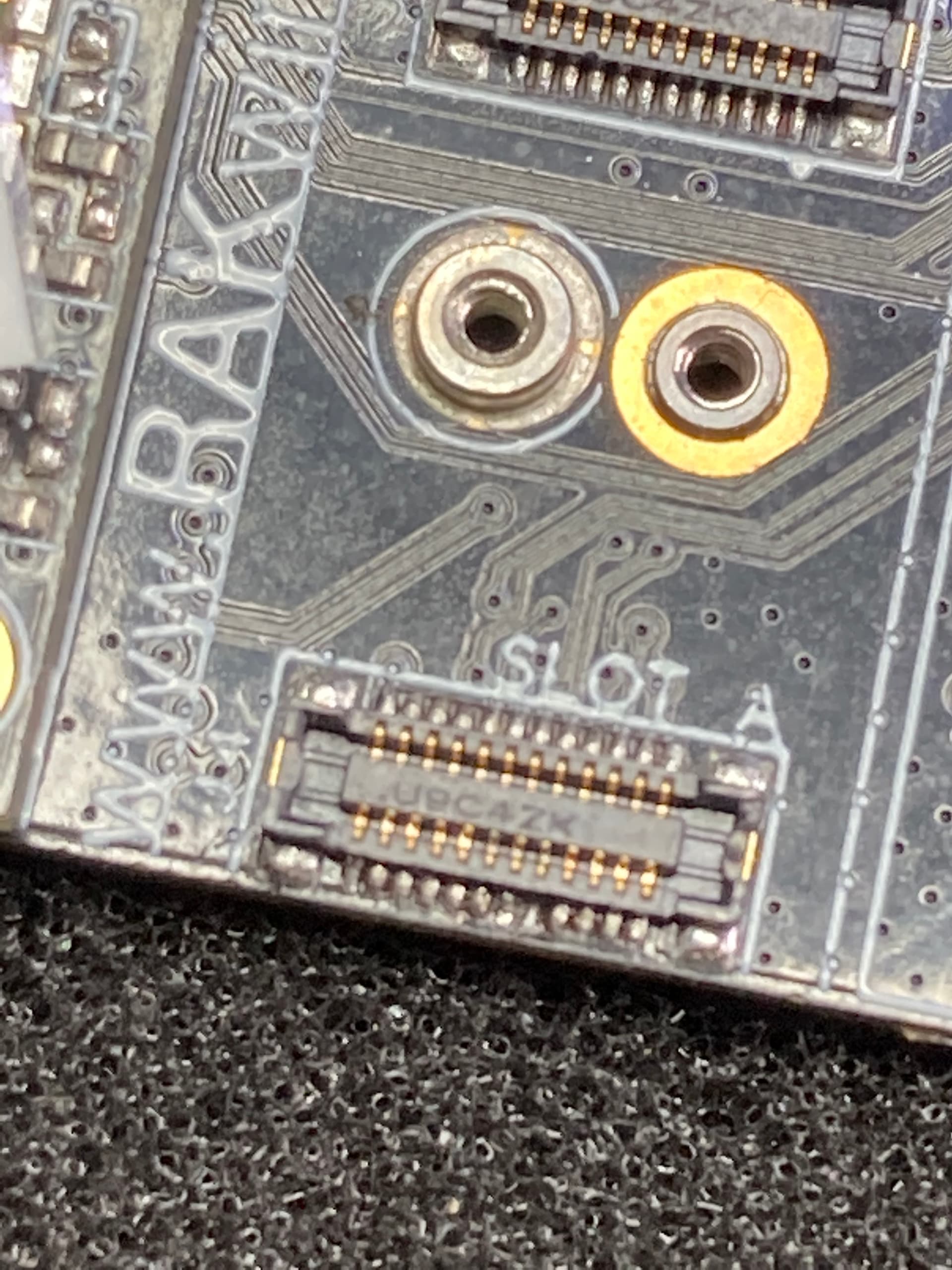
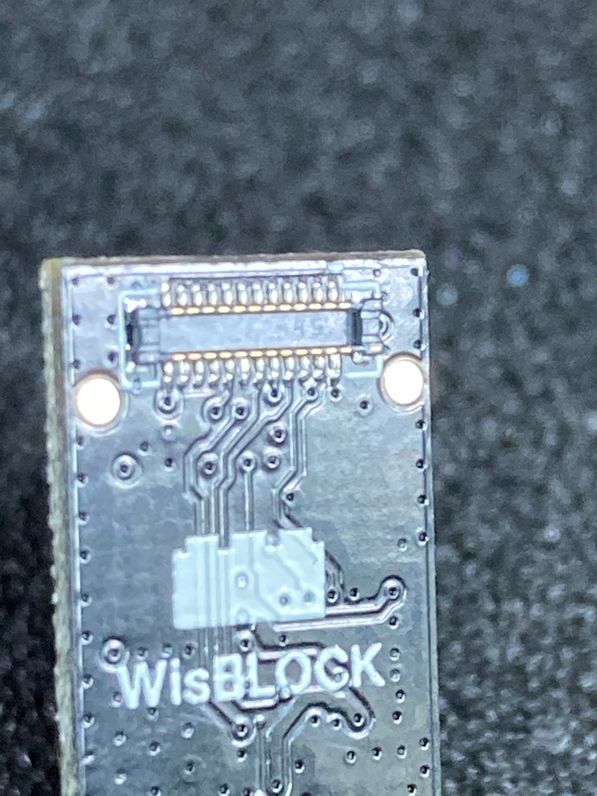
Can you try to make a good picture of the connectors on the RAK5005-O and RAK12500. I want to make sure there is no damage on the connectors itself.
Like these:
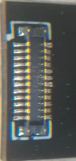
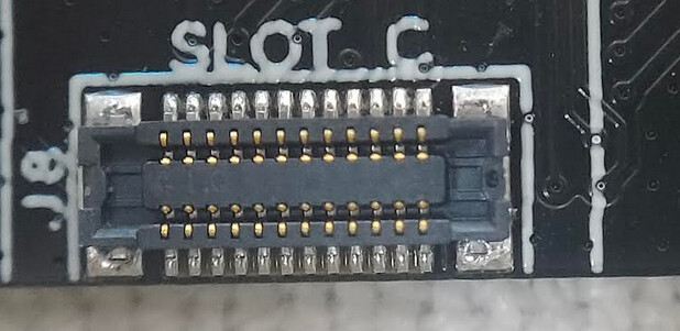
These images are the best that I could manage I’m afraid @beegee.
So this morning, we put the GPS chip into another board. This board worked as expected with the module connected to slot A, however when we placed the module into slot C the call to gnss.begin() fails as on the other boards.
Also, today the board that I was having trouble with yesterday, now the module works in slot C and not in slot A!! I had my colleague watch me as I performed the steps (you know get someone else’s eyes on the matter just to make sureI’m not doing anything stupid), and he was left as baffled as I.
It’s the inconsistency of it that I simply do not understand. It can be the case that with the USB attached, the board powers up and the program runs correctly, and then after pressing the reset button, the board cannot then locate the GPS module but that is not consistent behaviour either.
Hello Bill,
The images are good enough. I just wanted to see the connectors, because I personally damaged several of them (thick fingers and impatient when connecting).
I am kind of lost with your problem, I am playing with WisBlock modules everyday, as I have access to the first prototypes of new modules. But I never experienced anything like your problem.
Did you try to run the very simple Example Code on the base board / RAK12500 that shows these strange behaviour?
#include <Arduino.h>
#include <SparkFun_u-blox_GNSS_Arduino_Library.h>

bool Initialise();

SFE_UBLOX_GNSS _gnss;

void setup()
{
  Wire.begin();
  vTaskDelay(10);
  while(!_gnss.begin())
  {
    digitalToggle(LED_BLUE);
    digitalToggle(LED_GREEN);
    vTaskDelay(1000);
  }
}

void loop() {
}
This to me, is even more simple than the example you pointed to, and this works “sometimes” and doesn’t work other times … what baffles me the most is that BOTH of the boards I am working with were working perfectly fine on Saturday, and then yesterday when I got back to them (because it was a bank holiday here on Monday), they just stopped working.
BatteryWatchdog_t BatteryWatchdog;
FlashChoreographer_t* startup_light;
TickType_t _lastRun;

void setup()
{
  time_t timeout = millis();

  Serial.begin(115200);
  startup_light = new FlashChoreographer_t();
  startup_light->CreateTask(FAIL_LED);
  while (!Serial && ((millis() - timeout) < 5000))
  {
    startup_light->Flash(1);
    vTaskDelay(250);
  }
  lora_rak4630_init();
  Wire.begin();
  while(!gpsUnit.Initialize())
  {
#ifdef CONNECTED_FOR_DEBUG
    Serial.println(F("u-blox GNSS not detected at default I2C address."));
#endif // CONNECTED_FOR_DEBUG
    digitalToggle(SUCCESS_LED);
    digitalToggle(FAIL_LED);
    vTaskDelay(500);
  }

  digitalWrite(SUCCESS_LED, LOW);
  digitalWrite(FAIL_LED, LOW);

  BatteryWatchdog.CreateTask();

  gpsTaskMaster.Initialize(BatteryWatchdog.GetMailBox());
  RadioTransmitter.Initialize(SUCCESS_LED, FAIL_LED);
  gpsTaskMaster.CreateTrackerTask(&gpsUnit);
  gpsTaskMaster.CreateReporterTask(&RadioTransmitter);
}

void loop() { vTaskDelay(pdMS_TO_TICKS(50)); }
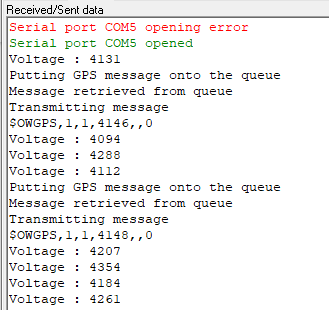
BatteryWatchdog_t is a task whose responsibility is to check the battery voltage and then overwite the message in a Mailbox (queue with only one entry which is never removed, but is overwitten with new values as they change). gpsTaskMaster is a class which wraps two OS Task instances, one task (TrackerTask) is responsible for collecting data from the GPS module and placing that data onto a queue, which the other (ReporterTask) removes, formats and passes over to the RadioTransmitter
This is the code which was working as expected when I finished up on Saturday. Yesterday morning we had a brief discussion here and decided that we would now like to make sure that the program does not attempt to start up the radio or the GPS module if the battery charge is below a specified level. The following is the change I made to achieve that.
- I added
#include "BatteryReader.h"inmain.cpp - Immediately prior to the call to
lora_rak4630_init();in thesetupfunction shown above I addedif(BatteryReader_t::ReadVoltage() <= LOWEST_ALLOWED_BATTERY_VOLTAGE) { return; }
which would stop all board initialisation -this would leave the board powered on, but with a program with would simply run the loop function, so that we can charge the battery without it being dsicharged further.
This is the BatteryReader.h file (just for clarification of what it is doing)
typedef class ClsBatteryReader
{
private:
    static const uint32_t vbat_pin = PIN_VBAT;
public:
    static float ReadVoltage(void)
    {
        float raw;
        raw = analogRead(vbat_pin); // Get the raw 12-bit, 0..3000mV ADC value
        return raw * REAL_VBAT_MV_PER_LSB;
    }
} BatteryReader_t;
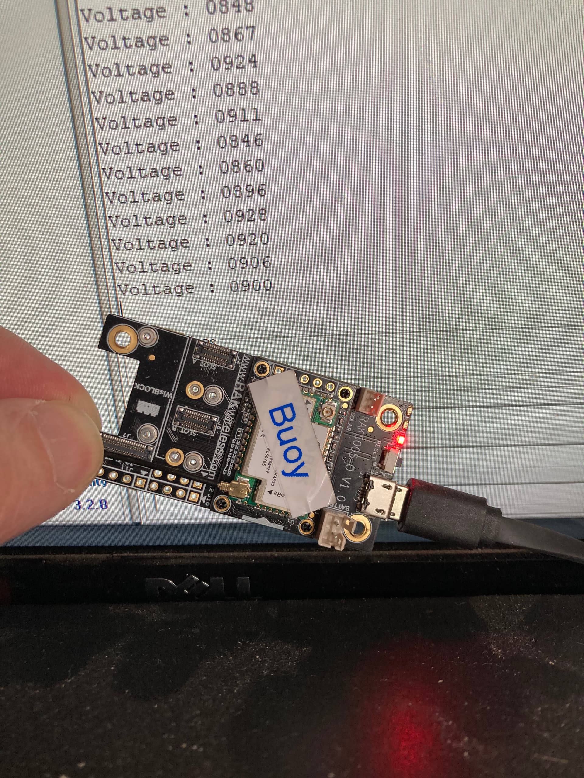
When I uploaded that change to the board (which was connected via USB) I noticed that the board was not transmitting any data (we flash the onboard blue LED when a transmission is completed and it was not flashing). I opened comms on the connected port and there was no information coming through, which then led me to believe that the BatteryReader test had failed and we were now in the empty loop().
So I made a further change:
void loop()
{
  Serial.printf("Voltage : %04.f", BatteryReader_t::ReadVoltage());
  vTaskDelay(pdMS_TO_TICKS(500));
}
Then, when I ran the program and opened up the COM port, I viewed readings like the following
Voltage : 0809
Voltage : 0854
Voltage : 0906
Voltage : 0862
So it was only registering as 0.8V. Something which I found to be incredibly odd, since the board was currently being powered by the connected USB.
I then swapped the USB cable out thinking that maybe there was a fault on that, but no, I got hte same readings. I had decided that there must be something wrong with the code and that I must have introduced some other change that had resulted in these strange readings, so I reverted all of my changes, uploaded the program to the board and that is when the GPS unit started failing consistently in an inconsistent manner (if that makes sense)