I’m looking at the documentation for the RAK4630 KR920 module and have some questions.
We plan to use the RAK4630 KR920 together with an ESP32S3. The ESP32S3 will connect to and control the RAK4630 KR920, and we need to send data to a PC. Some information will also be stored in the ESP32. However, we are not sure how to connect the RAK4630 to the ESP32S3. Could you please advise on the recommended interface?
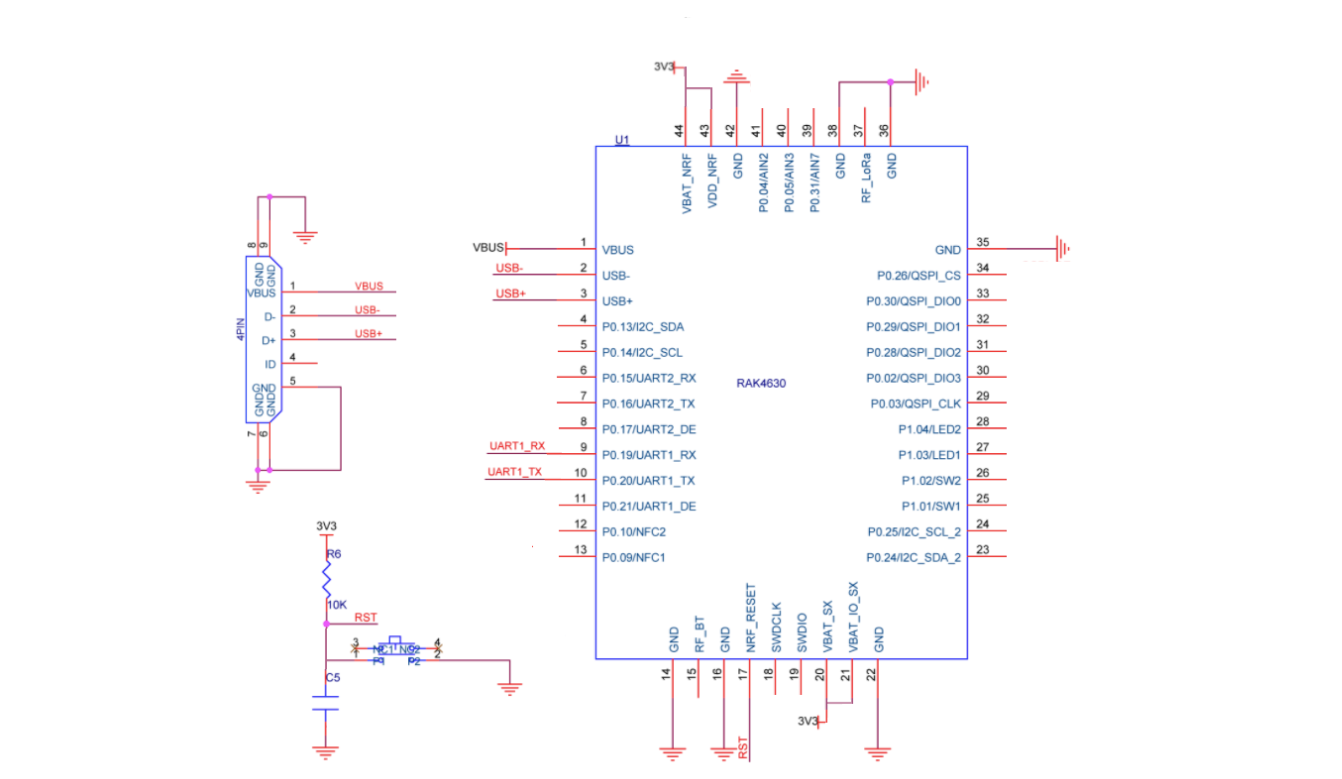
I could not find a detailed pinout explanation in the document. I only see pin names such as UART1_RX and I2C_SDA. Could you please provide a pinout table with explanations? For example:
Pin name: I2C_SDA
Description: Serial Data Line
I see the USB connection for the RAK4630 KR920 in the document, but it is not a USB Type-C connector. Could you please tell me how to connect it to a USB Type-C port?
For the communication between RAK4630 and the ESP32, will it be using AT commands?
I don’t think you can connect the RAK4630 to the ESP32 through USB. As far as I know, both are USB devices, none of them is a USB hosts.
Are you using RUI3 AT command firmware on the RAK4630 or are you using a custom application?
If you are using a custom application, are you using RUI3 API?
In the Pin Definition section for the RAK4630 you see the GPIO number and the alternative usage, e.g.
Pin No.
Name
6
P0.15/UART2_RX
means on pin 6 of the WisDuo module the GPIO 0.15 is connected and its usage is RX for the second UART.
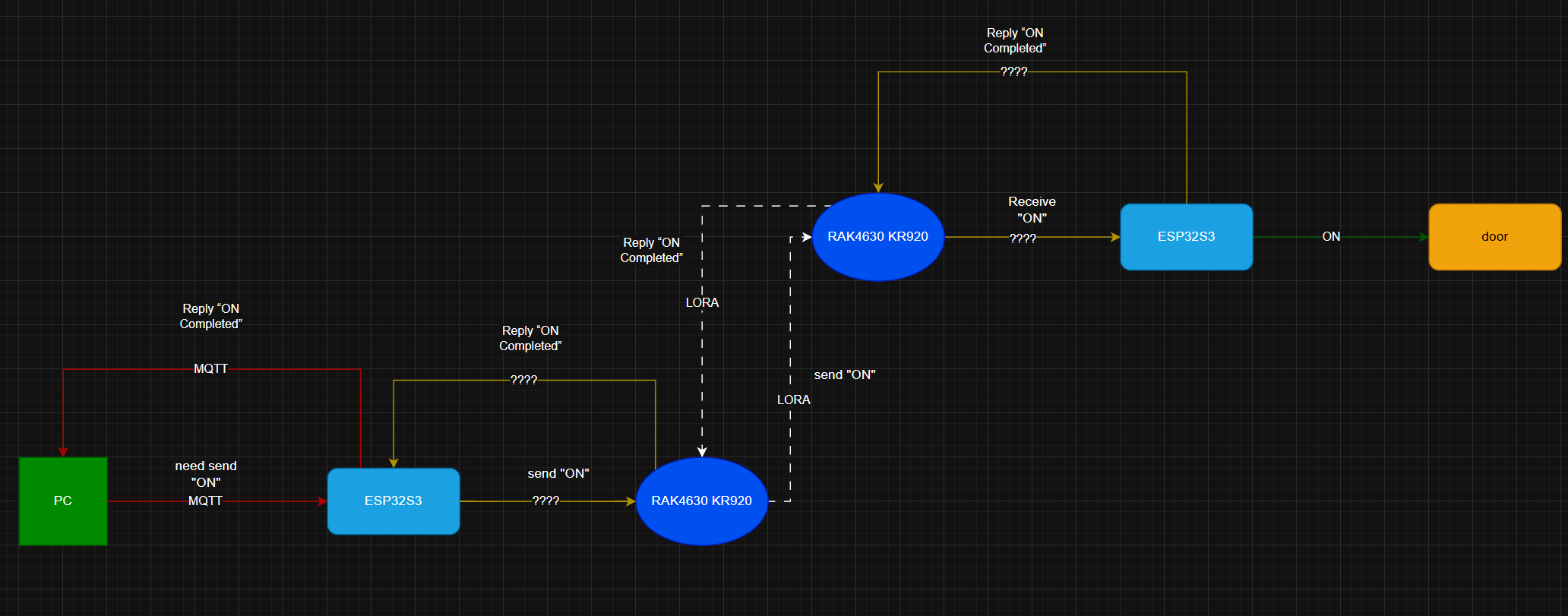
I would like to control a RAK4630 module from a PC to send custom commands to another RAK4630, which would then lock or unlock a door. This is a hypothetical application.
As far as I understand, the RAK4630 cannot communicate directly with a PC for control purposes. Therefore, I plan to connect an ESP32 to the RAK4630 and store the required control commands in the ESP32.
Transmitting side:
The PC tells the ESP32 via Wi-Fi/MQTT that the RAK4630 needs to send an ON/OFF command. The ESP32 then passes the corresponding command to the RAK4630 for transmission. Should this command be sent to the RAK4630 via UART, SPI, or another interface, so that the RAK4630 can send it to the target RAK4630 device?
Receiving side:
After the target RAK4630 device receives the command, it informs the ESP32 via UART that reception is complete. The received data is then passed to the ESP32, which controls the locking or unlocking action. I would also like to ask the same question for the receiving side: should the received data be passed from the RAK4630 to the ESP32 via UART, SPI, or another interface?
I have also attached a communication block diagram for your reference.
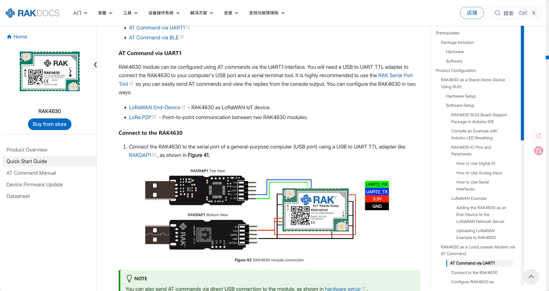
Regarding the USB interface: it will be used to flash custom firmware to the RAK4630. However, the documentation only provides a 4-pin Micro USB schematic, not a USB Type-C schematic. I would like to know how to wire the USB Type-C connection.
Could you please advise on the above questions? We are currently designing the PCB.
Please contact me if you need more information.
Thank you for your help.
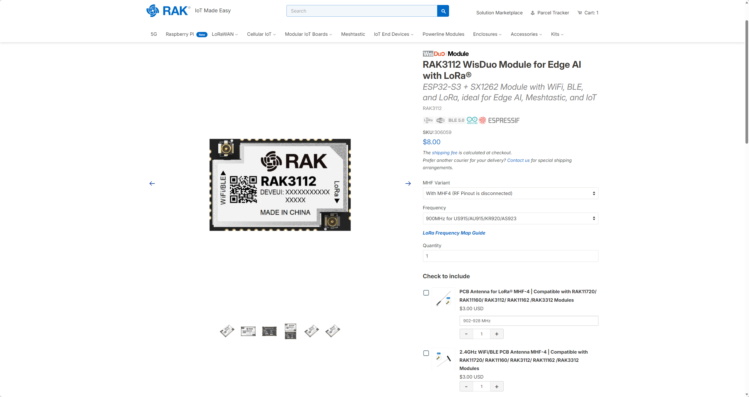
Just a suggestion, instead of using the ESP32 + RAK4630 combination, why don’t you use the RAK3112 module? This module is based on an ESP32-S3 and has its own LoRa transceiver.
You could use the ESP32 WiFi to connect to MQTT and directly send the command over LoRa to the receiver part to control the door.
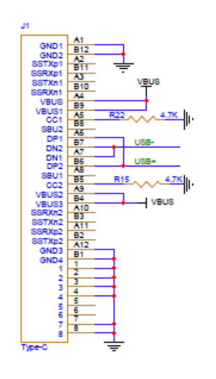
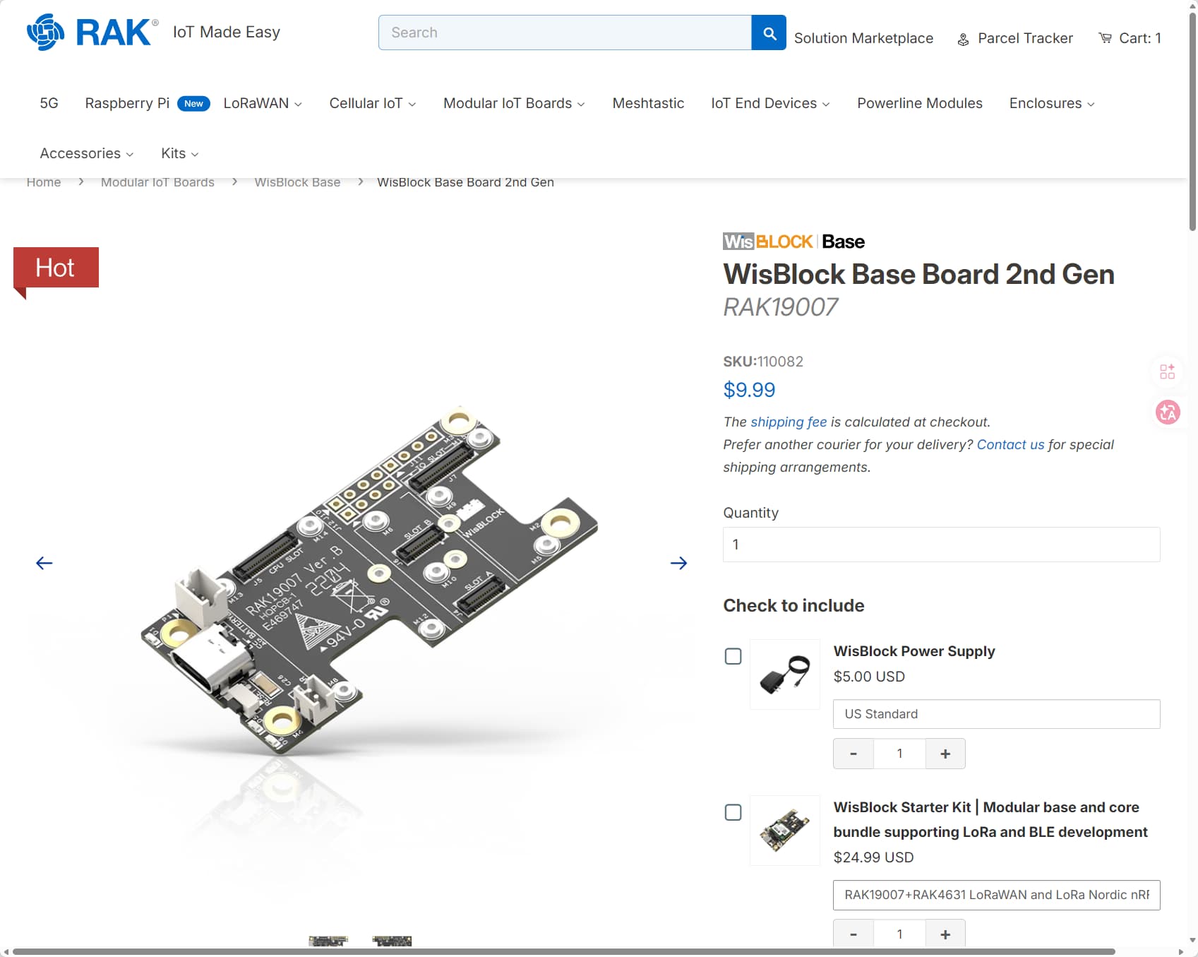
Regarding connecting the USB pins to a USB C connector, here is the schematic of an USB C connector we use on our WisBlock Base Boards:
The pin out should be “standard”, but you still should check with your specific connector how to connect the USB- and USB+ lines coming from the RAK4630.
Sorry, we do not share the PCB files, but you can find the schematics in our Documentation Center. RAK4631 ==> RAK4630 as WisBlock Core module with connector for the RAK19007 Base Board RAK19007 ==> WisBlock Base Board with power supply and interconnection for 4 sensor modules and 1 IO module