
Hi @Alangward
I never tried that. A good point to start searching might be the u-blox MAX-7 data sheet => https://www.u-blox.com/sites/default/files/products/documents/MAX-7_DataSheet_UBX-13004068.pdf
Hi @beegee
I had already discovered that document. I have also downloaded
u-blox 7 Receiver Description Including Protocol Specification V14.
I’m a little worried that this device appears to be ‘end-of-life’ on the u-blox web-site.
So I’m wondering how long you will be able to maintain supplies of the 1910. If our design is critically dependent on it we may run into problems in the future.
Anyway, I see it supports the UBX protocol as well as NMEA so I intend to investigate whether this gives us more control. I’ll let you know how I get on.
Thanks
Alan
I am thinking about a hardware change on the RAK12500. Having the RX/TX disconnected and a solder jumper for people who needs serial communication. But that is of course nothing that will be available fast.
That would be a good move from our point of view - future proof our solution.
Thanks
Alan
Hi,
I have received and assembled this base board with the RAK 18001 buzzer and the RAK12500 GPS. Everything works fine except that I cannot get the buzzer to work - I assume I am using the wrong pin - I have tried changing it with no improvement.
Thanks
Alan
Hi Alan,
Which Slot are you using for the RAK18001? Here is an overview for the IO to be used depending on the Slot number: RAK18001 WisBlock Buzzer Module Datasheet | RAKwireless Documentation Center
One thing we found about the Tone() function in Arduino. It can happen that the IO is staying on HIGH level after the tone was played. You need to use digitalWrite(IO, LOW) after finishing to play a tone.
Hi Brent,
That data sheet refers to the 5005 base board which has the slots marked. I am now using a 19003 base board that does not have the slots marked. I experimented with PIN numbers but cannot find one that works.
Thanks Alan
Hi Alan,
Yes, the silk screen was incomplete, we correct this in the next production batch.
Here is the information for the slots:
Slot Names
And here is the information about the sensor slot pin assignment"
Slot Connector
Even the slots are marked as A and B, we used WB_IO3, 4, 5 and 6 to keep the IO1 and IO2 free for other uses.
Hi Bernd,
There seems to be a problem with the buzzer module on the 19003 base board.
I found that if I used WB_I05 (rather than WB_I03 that I had been using on the 5005) with my existing application then the buzzer worked as expected once and then the device crashed and restarted.
So I thought I’d try it with the buzzer demonstration sketch that plays a tune - all I got was a series of clicks rather than notes. And I could not reflash the device from PIO without double clicking the reset button.
Note that I also have the GPS ZOE-M8Q installed on slot B.
Thanks
Alan
Hi Allan,
Slot A uses WB_IO3 and WB_IO4 so if the buzzer is in Slot A you should use WB_IO3
WB_IO5 is connected to the GNSS module and is the 1PPS output of the ZOE-M8Q. so it should not be setup as output. The reason for the crash is most likely that the 1PPS signal from the GNSS module and the PWM signal from the RAK4631 were fighting against each other.
Hi Bernd,
I was originally using WB_I03 as that as how I have it set for the 5005 base board. That does not work. The only way to get any sound from it is to use WB_I05.
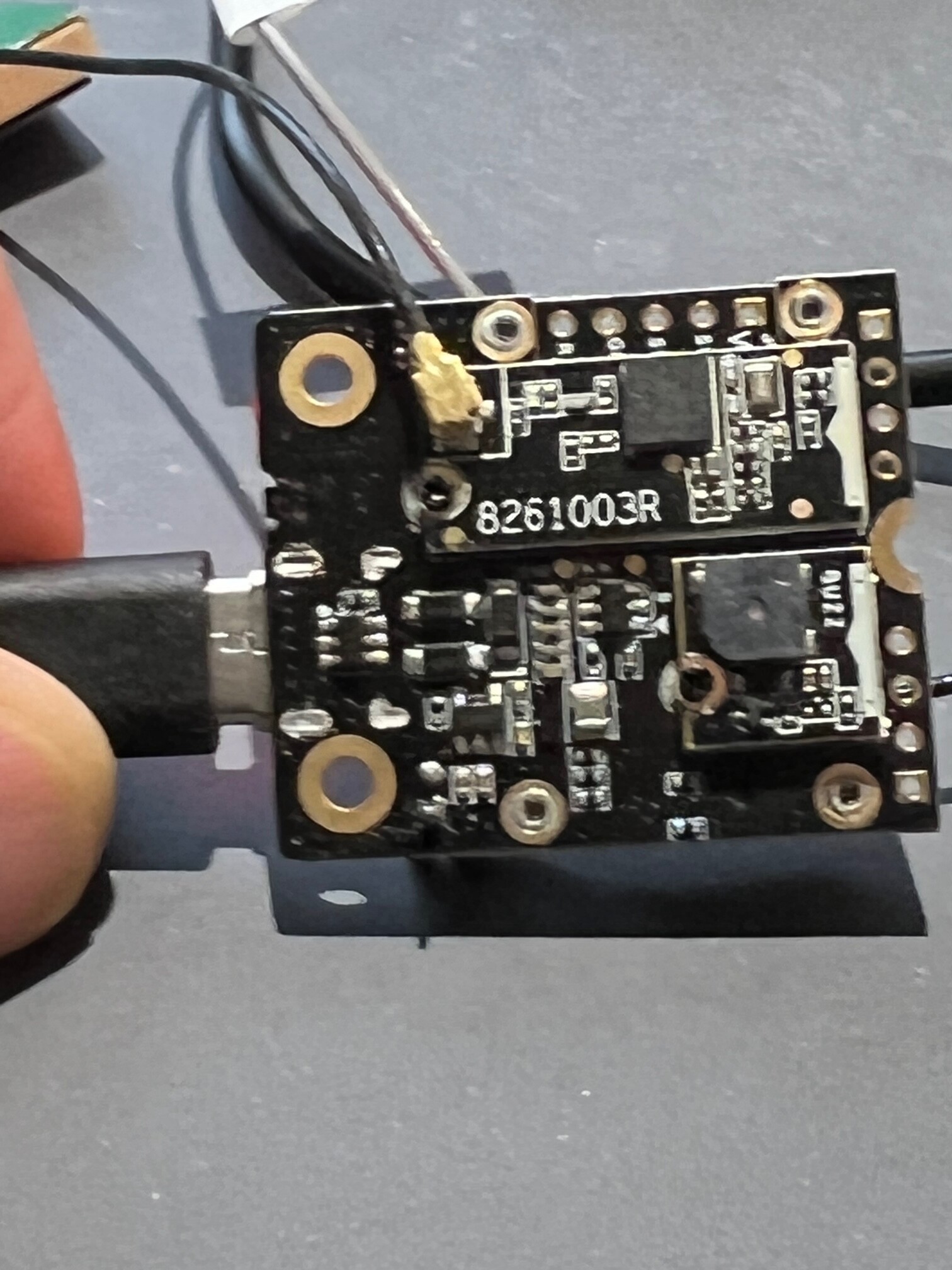
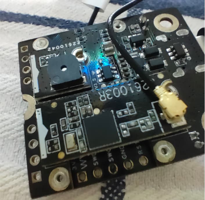
I’ll try and send you a photo of my set up to confirm the physical placement of the components
Alan
Just setup the same 
You found a mistake in our documentation.
The small slot uses WB_IO5 and WB_IO6 so the Buzzer will work over WB_IO5 (confirmed with the buzzer example).
But our documentation says otherwise. Checking with team right now.
Verified with the buzzer example code, WB_IO5 plays the tune.
But there seems to be a problem with the USB Serial when it is not initialized. I found the same problem that the USB didn’t work after I uploaded the Buzzer firmware. Needed to reset to get it back to work.
Still investigating this problem.
But, if I use the buzzer example I get just clicks rather than the tune. And I still have the problem with my actual application where it appears to crash after playing the correct note - but it might just be the USB serial failing as my only evidence is that the monitor output fails.
Alan
It is strange that the simple buzzer example doesn’t work, it worked out of the box (after selecting the correct WB_IO5) for me.
For your actual application, can you share your code so that I can have a look into it?
Hi Bernd,
Rather than you spending hours trying to unscramble my code I thought I’d put together a reproducible case based on the buzzer example.
I added some printing and it is behaving in a very weird way.
===================================================
/**

   @file RAK18001_Buzzer.ino

   @author rakwireless.com

   @brief period buzzer test and play a funny song

   @version 0.1

   @date 2020-12-28

   @copyright Copyright (c) 2020

**/

#include <Arduino.h>

#include <SPI.h>

#include <Wire.h>

#define BUZZER_CONTROL  WB_IO5

//This part is the note and rhythm of the song

#define NTC0 -1

#define NTC1 262

#define NTC2 294

#define NTC3 330

#define NTC4 350

#define NTC5 393

#define NTC6 441

#define NTC7 495

#define NTCL1 131

#define NTCL2 147

#define NTCL3 165

#define NTCL4 175

#define NTCL5 196

#define NTCL6 221

#define NTCL7 248

#define NTCH1 525

#define NTCH2 589

#define NTCH3 661

#define NTCH4 700

#define NTCH5 786

#define NTCH6 882

#define NTCH7 990

#define WHOLE 1

#define HALF 0.5

#define QUARTER 0.25

#define EIGHTH 0.25

#define SIXTEENTH 0.625

int tune[]=                 //List the frequencies according to the spectrum

{

  NTC5,NTC5,NTC6,

  NTCH1,NTC6,NTC5,NTC6,NTCH1,NTC6,NTC5,

  NTC3,NTC3,NTC3,NTC5,

  NTC6,NTC6,NTC5,NTCH3,NTCH3,NTCH2,NTCH1,

  NTCH2,NTCH1,NTCH2,

  NTCH3,NTCH3,NTCH2,NTCH3,NTCH2,NTCH1,NTCH2,NTCH1,NTC6,

  NTCH2,NTCH2,NTCH2,NTCH1,NTC6,NTC5,

  NTC6,NTC5,NTC5,NTCH1,NTC6,NTC5,NTC1,NTC3,

  NTC2,NTC1,NTC2,

  NTC3,NTC5,NTC5,NTC3,NTCH1,NTC7,

  NTC6,NTC5,NTC6,NTCH1,NTCH2,NTCH3,

  NTCH3,NTCH2,NTCH1,NTC5,NTCH1,NTCH2,NTCH3,

  NTCH2,NTC0,NTCH3,NTCH2,

  NTCH1,NTC0,NTCH2,NTCH1,NTC6,NTC0,

  NTCH2,NTC6,NTCH1,NTCH1,NTCH1,NTC6,NTC5,NTC3,

  NTC5,

  NTC5,NTC6,NTCH1,NTC7,NTC6,

  NTCH3,NTCH3,NTCH3,NTCH3,NTCH2,NTCH2,NTCH1,

  NTC6,NTCH3,NTCH2,NTCH1,NTCH2,NTCH1,NTC6,

  NTCH1,

};

float durt[]=                   //List the beats according to the notation

{

0.5,0.25,0.25,

1.5,0.5,0.5,0.25,0.25,0.5,0.5,

1+1+1,0.5,0.25,0.25,

1.5,0.5,0.5,0.5,0.25,0.25,0.5,

1+1+1,0.5,0.5,

0.5,0.5,0.5,0.25,0.25,0.5,0.25,0.25,0.5,

0.5,0.5,0.5,0.25,0.25,1+1,

0.5,0.5,0.5,0.5,0.5,0.5,0.5,0.5,

1+1+1,0.5,0.5,

1.5,0.5,0.5,0.5,0.5,0.5,

1.5,0.5,1,0.5,0.25,0.25,

1.5,0.5,0.5,0.5,0.5,0.25,0.25,

1+1+1,0.5,0.25,0.25,

1,0.5,0.25,0.25,1,1,

0.5,0.5,0.5,0.5,1,0.25,0.25,0.5,

1+1+1+1,

0.5,0.5,0.5,0.5,1+1,

0.5,0.5,0.5,0.5,1.5,0.25,0.25,

1.5,0.5,1,0.25,0.25,0.25,0.25,1+1+1+1,

};

int length = 0;

void setup()

{

  // Initialize Serial for debug output

  Serial.begin(115200);

  delay(5000);

  Serial.println("Starting buzzer");

  delay(1000);

  pinMode(BUZZER_CONTROL,OUTPUT);

  length=sizeof(tune)/sizeof(tune[0]);   //Calculation length

}

void loop()

{

  for(int x=0; x < length; x++)

  {

    tone(BUZZER_CONTROL,tune[x]);

    delay(500*durt[x]);   //Here it is used to adjust the delay according to the beat. The 500 index can be adjusted by myself. In this music, I find that 500 is more suitable.

    noTone(BUZZER_CONTROL);

  }

  delay(2000);

    Serial.println("next loop");

}
==================================================
Alan
Something weird indeed. I see your problem and I solved it. But I am not sure why my changes get it to work.
I replaced the two includes
#include <SPI.h>
#include <Wire.h>
with
#include <Adafruit_TinyUSB.h>
And then in setup() I replaced
delay(5000);
with
while (!Serial) {};
And everything works fine.
Hi Bernd,
I noticed that my libraries were fairly out of date and I wondered if that might be the root of my problem. So I updated them.
But now it can’t find ‘variant.h’. I know I’ve had this problem before - I can’t remember how I solved it previously.
Thanks
Alan

Follow this guide to get back RAK4631 on PlatformIO: WisBlock/PlatformIO at master · RAKWireless/WisBlock · GitHub
Thanks for that. I’ve now book marked it. So hopefully I’ll remember next time.
However, the buzzer is still not working. I tried the changes you suggested and it appears to hang on the while(!Serial({}); statement.
If I remove that and replace the delay then I get one short ‘pip’ and the device resets - and so on.
With my app I get one clear tone; the second time it’s just a ‘pip’ and then resets. There seems to be some correlation with the GPS getting a fix, but I can’t be sure of that.
I have tried 2 devices and they both behave the same.
Thanks
Alan