
I am making a custom PCB based on RAK 4630. I want to use JLCPCB for it. The documentation of the RAK 4630 is a little bit confusing regarding the power use. Is there any reference design to start my PCB with? I want to only use the RAK 4630 as my MCU with couple of components (GPS, accelerometer, RTC ) all this designed for low power consumption and to be powered with a SAFT LiSOCl 14500 battery. Can you provide a reference design on how to feed components from the RAK 4630_
Welcome to RAK forum @Bright117
You can refer on this section - RAK4630 WisDuo LoRaWAN+BLE Quick Start Guide | Setup & Configuration
You must use the High-Voltage Mode.
Hello Carl. Following the recommendation of high voltage mode, and from this datasheet: RAK4630 LoRaWAN + BLE Module Datasheet | Specs & Features it says the following:
But in the RAK 4630 RAK4630 WisDuo LoRaWAN+BLE Quick Start Guide | Setup & Configuration
It says the following:
" 2. High Voltage Mode
In high voltage mode, you can directly connect your external source (usually battery) to VBAT_NRF pin. VBAT_NRF should be higher than 3.3 V which is the nominal operating VDD level and must be left floating. The maximum allowed voltage for VBAT_NRF is 5.5 V.
This configuration is required in nRF52840 inside the RAK4630 to operate in High Voltage Mode in which internal DC/DC and REG0/REG1 are enabled. This is the default setting on the RAK4631 WisBlock Core which uses RAK4630 module."
They are using a special rail from 3V3 in the high voltage mode, apparently the default setting on the RAK 4631 WisBlock, and also there VDD_NRF is left floating.
My question is the following:
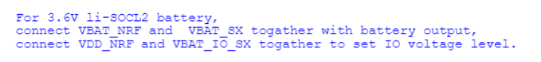
Is it ok if I power my custom PCB only from a Li-SOCL2 3.6V battery (BAT_+ and BAT_- terminals), and make this connections:
BAT_+ → VBAT_NRF
BAT_+ → VBAT_SX
VDD_NRF → VBAT_IO_SX
GND → BAT_-
USB+ → Not connected
USB- → Not connected
VBUS → Not connected
Considering that at some point the battery will reach less than 3.3V in its life time and hence the high voltage mode will nort work properly,
My PCB will be used for a custom tracker so the lowest power consumption is required.
Hi @Bright117 ,
You are basically powering the nRF52 and SX1262 with 3.6V so it should be ok. You are operating in High Voltage mode.
You have to take note though that Li-SOCl2 has high internal resistance. You have to check the specs of your battery if it will be able to sustain the peak current of radio module during TX. Else, you might need to add capacitor or power conditioning circuit.
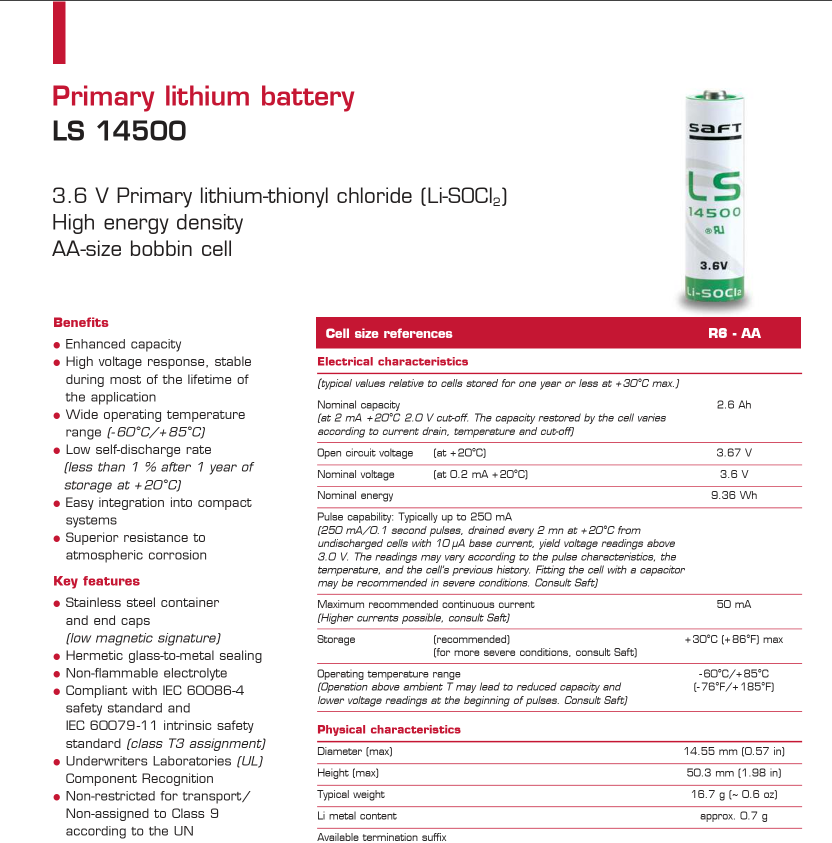
I have already checked, 50mA continuos current,
Blockquote Pulse capability: Typically up to 250 mA (250 mA/0.1 second pulses, drained every 2 mn at +20°C from undischarged cells with 10 µA base current, yield voltage readings above 3.0 V. The readings may vary according to the pulse characteristics, the temperature, and the cell’s previous history. Fitting the cell with a capacitor ,
Hi @Bright117 ,
I am not sure if this will be enough without power conditioning circuit. It can only have 250mA at 100msec. For SF7 with few bytes of payload it can possibly work. Check the airtime requirement here - https://avbentem.github.io/airtime-calculator/ttn/eu868/10
Having measurement on oscilloscope for timing is recommended since you only have 100mSec to have a spike. Many designs I see have external power conditioning circuits for this type of batteries.
1 Like
This topic was automatically closed 10 days after the last reply. New replies are no longer allowed.