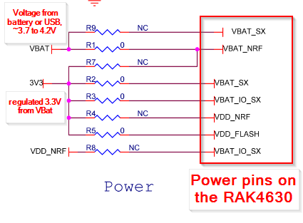
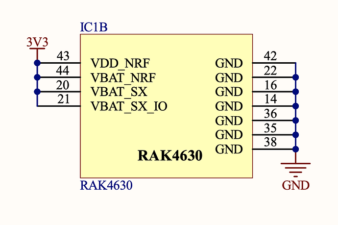
@beegee here’s what is in our schematic, I think this is what you are looking for?
There could be the problem here.
The RAK4630 is internally designed to use VBAT_NRF to generate its own GPIO supply. Therefor VBAT_NRF should be higher than 3.3V. As you can see in the schematic part I posted, we have VBAT_NRF connected to VBAT which is between 3.7V and 4.2V.
I am not sure whether this could cause a supply problem while BLE is active that could influence the SX1262 transceiver.
I have no setup to test your supply configuration, but I will forward this to our R&D team. They are in Chinese New Year, so an answer might not be back before beginning of February.
On your custom PCB, do you have an option to connect VBAT_NRF to another voltage than the 3.3V?
Hi @beegee!
We do have that option. We are actually making a new PCB revision right now to deal with a couple other issues that came up during testing. I’m passing this info along to our PCB designer right now.
I’ll let you know what he says, surely other people building products based on the 4630 might find this useful!
– Nathan
Hi Nathan,
Usually we use the Breakout Boards for the WisDuo modules as reference schematics.
Unfortunately for the RAK4630 we never made such Breakout Board.
I will check with our Documentation team if we can add a reference schematic with these details.
A reference schematic would be very helpful. I have found something a little confusing here. In the RAK4631 power supply schematic section you shared, the notes say that VBAT_SX and VBAT_NRF should both be supplied 3.7 to 4.2V from the battery or USB.

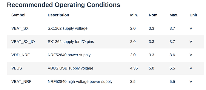
However, the 4630 documentation says that VBAT_SX should be supplied 3.3V normally, 3.7V max. The 3.7-4.2 range in the schematic segment you shared would seem to be out of spec, based on the documentation. The same docs say that VBAT_NRF should be supplied between 2.5 and 5.5V, so 3.3 from the regulated supply should be just fine. Our power supply circuit can supply up to 500mA at 3.3V
What am I missing here? Do you have any insight into that discrepancy? We referred to the RAK documentation when designing the board.
Since I’m designing a custom board with RAK4630, I’m watching this thread closely…
In my case I’ll be powering the board directly from a LiFePo4 battery (3.6v when charged) I’ve not planned to have a regulator circuit (only the LiFePo4 battery charger IC)
Is it safe to power RAK4630 at 3.6V on all VDD_XX pins? as Nathan said probably there’s a discrepancy between your schematic and recommended operating conditions.
Regards
@nmcminn
The error is in the documentation. In our WisBlock Base Boards VBAT is directly connected to the rechargeable battery which has 3.7 to 4.2 V, depending on its charging status.
@javier.nr
I never tried to run the RAK4630 from 3.6V. It is close to the upper max specs for VDD of the SX1262 (3.9V) and of the nRF52 (3.9V). A spike on the voltage could cause damage.
Beside of that, I expect the same problems if all supply pins are tied to the same voltage.
The nRF52 in the RAK4630 is designed to to use the DC/DC option. I couldn’t find the details in the datasheet, but you are not the first customers who have problems when VBAT is the same level as the 3.3V input.
Hello bernd!
LiFePo4 chemical will have 3.6v at maximum when fully charged, so based on max spec probably it’s okay as the battery will never reach 3.9v?
As DC/DC option is probably something inside nrf52? Can be changed on user side? Sorry to ask, never worked with Nordic Chip and I want to make sure the board will work with supply at the same voltage on all VDD_XX pins (if I can, I want to avoid voltage regulator)
Thanks for your attention
@nmcminn
I double checked documentation and schematics.
VBAT_SX is tied to 3.3V, not to VBAT and the documentation is correct, max is 3.7V.
VBAT_NRF allows up to 5.5V and is tied to VBAT.
No mistake in the documentation.
@javier.nr
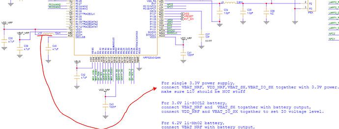
It cannot be changed to LDO as there is a coil for the DC/DC under the metal hood that would need to be removed.
Hello Bernd,
Now I understand what you mean, and also I’ve found here the schematic
So probably the coil to remove is L10, since it couldn’t be removed I will change my plans to include a 3v3 low dropout regulator. Any candidate/suggestion for this LDO (I mean very low quiescent current)?
In summary:
- VBAT_NRF and VBAT_SX to 3.6V (directly to battery).
- VDD_NRF and VBAT_IO_SX to 3.3V from regulator.
Many thanks for your attention, and excuse me @nmcminn for hijacking your thread, as you said:
It was super useful to me ![]()
PS. Next RAK4630 revision can include a solder bridge underside to bypass L10? ![]()
LDO is not the best solution when you want lowest quiescent current.
In a new design where we will have supply from 3.6V LiSOCl2 batteries only we use the RT6160 converter ==> https://www.richtek.com/Products/Switching%20Regulators/Buck-Boost%20Converter/RT6160A?sc_lang=en&specid=RT6160A
Wow @beegee superb support! Many thanks!
I was checking RT9080 and SGM6036 also, will study your part also.
new devices! great! ![]() …
…
Hi @beegee,
Were they able to solve the problem of +EVT:JOIN_FAILED_TX_TIMEOUT?
I have the same issue but in the RAK3172 module. I have a post with more details RAK3172 Radio Tx Problem.
I hope you can help me.
This thread is related to power supply mainly. The join fail was related to usage of BLE at the same time, the RAK3172 doesn’t have BLE, so it is not related to your problem.
Hi @beegee,
I believe there is a mistake in the documentation.
In the RAK4630’s datasheet we have:
In the RAK4631’s datasheet we have:
Both says a voltage for VBAT_NRF between 2.5V-5.5V is recommended, but here you say:
So, for the RAK4630 VBAT_NRF is recommended to be higher than 3.3V, and not higher than 2.5V as the documentation says.
Is that correct?
It is not an error.
VBAT_NRF should be higher than VDD_NRF, so you have to compare the minimum of VDD_NRF min with VBAT_NRF min.


