RAK3172 Radio Tx Problem

Hi Everyone,

I’m working on custom hardware with RAK3172 and I’m using LoRaWAN_End_Node (SingleCore) demo project. Also, I added a sensor temperature (TMP117 or STS40). First, I began with RAK3172 with IPEX and PCB fabricated in PCBWay with standard battery holders. I tested around five PCB and I had a good connection with Gateway LoRa. After that, I order to manufacture of the other six PCB but now with RAK3172 with no IPEX version with helical spring antenna soldered in the factory and I used a custom battery holder that was soldered by me. All PCBs works fine but suddenly some PCB stopped transmitting and I didn’t know why.

I started to investigate the problem and I found that I could program the chip by ST-Link but it was impossible to debug the code and debug console print 0x00000000 in ?? () then I suspected that something was wrong with programming to chip STM32WL. I read the internal memory with STM32CubeProgrammer I found a surprise that the code had only zeros in all directions. After that, I run the next code by the terminal:

STM32_Programmer_CLI -c port=swd mode=hotplug -dsecurity

This code allowed to me reprogramming and debugging again. When I run the code works well the communication with the temperature sensor (TMP117 or STS40) but doesn’t join to LoRa Network and I can’t send data to Gateway. Up to this point, I’m not sure that could kill my device but after I soldered two other PCBs, one of them works fine until I soldered the battery holder and the other PCB worked fine until I soldered cable to UART2 to monitor AT Commands. So, I’m suspecting that the radio is suffering damage when solder near RAK3172, is important to say that my soldering iron is basic and it doesn’t regulate temperature and could have reached very high temperatures. I think it may be the temperature is a cause of the damage in the radio because the RAK3172 datasheet says the operative range is -40°C to 85°C and the peak reflow temperature is 250°C.

Another important test was with RUI_4.0.0 firmware. I sent the command AT+TTX=5 and never received the OnTxDone in any of the five packets sent how to say in the datasheet.

I would like if someone to know about this issue and if it was possible the failure is caused by temperature Also I would like to know if the radio is dead or not through some test or command.

Thank you !!
Welcome to RAK forum @pablo.olguin .

Sharing some of my insights in your situation.

  1. It is always best to have good soldering work station to avoid unnecessary side effects while doing repair. Personally, I do not think rework using hotair to remove the module on PCB will immediately cause damage. There is metal shield on RAK3172 so it will be hard to see if there are any components that got affected while removing it on board. There are very tiny 0201 capacitors and resistor that is in the radio front end that could be affected while doing the repair.

  2. I probably suggest to update to the latest firmware v.4.0.5. We got good feedback on this latest version on issues related to flash and random hanging of modules.

  3. Probably a good test on radio is to see if it really transmit using SDR or spectrum analyzer. If not possible, maybe checking current spike while it transmit my be an indicator that the radio still attempts to transmit (not really sure if radio signal is really transmitted - but can be a good indication).

Hi @carlrowan ,

Thank you for your fast answer. I received your suggestion and I did some tests.

Update to the latest firmware RUI v.4.0.5 and works well when I sent AT commands. I set these commands:

AT+NWM=1
AT+NJM=1
AT+CLASS=A
AT+BAND=6
AT+MASK=0002
AT+DEVEUI= (My Values)
AT+APPEUI= (My Values)
AT+APPKEY= (My Values)
AT+JOIN=1:1:10:3

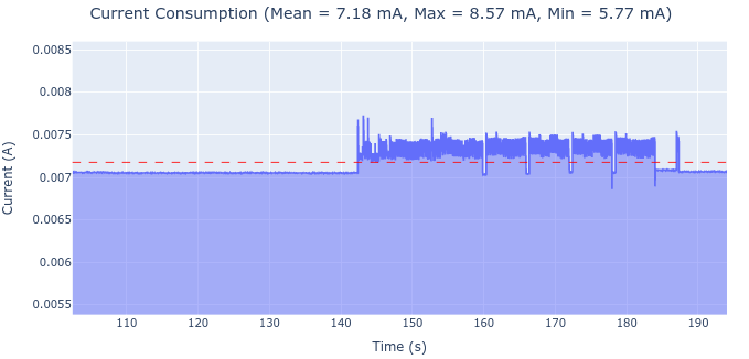
All commands respond with an OK but AT+JOIN send: +EVT: JOIN_FAILED_TX_TIMEOUT and I never received a join request in my gateway. I also monitored current consumption with INA229 evaluation board. In the first image, you can see when the device sleep by command AT+SLEEP and after sending AT+JOIN.

image

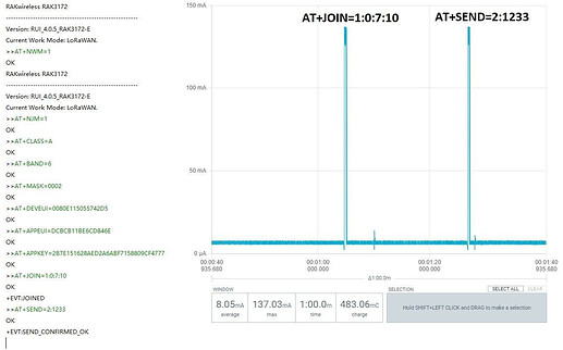
In the second image, you can see the current consumption when I sent AT+TTX=4 to test transmission but never received OnTxDone.

image

For all of these tests I think that my radio module is dead but I would like to know for why.

Hi @pablo.olguin ,

The modules seems trying to send an uplink. However, I do not see the devices goes to sleep on your first image. The current should be less than 10uA (can be as low as 2uA) if the device goes to sleep.

What is shown when you input AT+TTX=4?

I can’t really say why your Radio module is dead (if ever that is true). It can be damaged thermally, electrically, physically, etc. I forgot to say to erase first the memory of your module via STM32CubeProgrammer before uploading the latest firmware (might not be related but I have few experience before with customer to fix some strange issues).

@pablo.olguin , could you tell me how you measure the power consumption of the module?

Hi @G_eorge,

I used the INA229EVM board to measure the current consumption but now I bought a Power Profiler Kit II and It works better I recommend you.

Hi @carlrowan

In your last answer to my post, you say to me that the sleep current was wrong but this is because of the scale of my current meter INA229, I was interested in peak current then I set sensibility to higher currents to detect when It sends a join request to the gateway.

Also, you answer me what is shown when I send AT+TTX=4 and I obtain this:

AT+TTX=4

Tx Test: Packet 1 of 4
Tx Test: Packet 2 of 4
Tx Test: Packet 3 of 4
Tx Test: Packet 4 of 4

Finally, you tell me what to use STM32CubeProgrammer to erase memory before uploading firmware but I did.

I’m now thinking that the temperature is not the reason for the damage to the radio because another module died and it didn’t contact with the solder iron I’m suspecting an ESD discharge but I can’t confirm that.

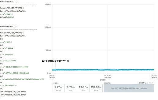
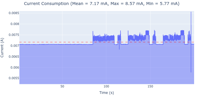
I bought the Power Profiler Kit II to have good measurements of current when I test the AT firmware. I did the next test: I selected two PCB one of them I know works well and I monitored the terminal and current and the other one I know doesn’t work and tested the same things

In this image, I test a good PCB and I can see the peak of the current of JOIN and SEND commands:

In this image, I test a bad PCB and I never see the peak of the current of the JOIN command:

(I know that the sleep current is not correct but I think is because use a serial module to communicate my PCB to PC, this is not important now, I want to resolve Tx first)

I have another doubt when a PCB fails I can´t reprogram it until run this code by terminal "STM32_Programmer_CLI -c port=swd mode=hotplug -dsecurity
" if use full chip erase from STM32CubeProgrammer I can’t reprogram my device. is it related to chip protection? Could this command cause the error?

On the other hand, I would like to explain the custom firmware that I uses before the problem to know if something of that could have died the module. I started the project with LoRaWAN_End_Node (SingleCore) but the version of danak6jq modifications with 1.2 version. I have seen that version 1.3 is available but I haven’t tested it yet. To this code add I2C communication to two different temperature sensors (TMP117, STS40), and works well. I also add IWDG and EEPROM emulation to save ADR when is changed by the downlink message. These two functionalities work well but I don’t know if some of these functionalities can damage the code and make it malfunction.

Thank you, I hope someone can help me.

1 Like

Hi @pablo.olguin ,

Determining the issue might be difficult. If it is ESD, it shouldn’t happen in all modules unless no care is done in handling the module/s (which I believe you handle properly).

We can now check the software side, but working with low-level custom implementation of IWDG and EEPROM is something that needs more investigation. Have you tried to implement the same custom firmware on a module (which previously works) but then stop working (RF not emitting signals)?