I’m interested in the using the RAK_Can module to test standard-can bus (not FD), however I’m using a ESP32.
Since I’m not very familiar with Arudino nor the layout, I don’t know what would be involved to port the RAK_Can driver to ESP32. Github has only a 13006 “.ino” example but I assume its other files that would need to be modified for the ESP32’s SPI?
The examples for the RAK13006 work with our RAK11200 ESP32 Core module.
The required library can be installed with the ArduinoIDE library manager, search for RAK13006 and you can find them.
Or you can install the library manually from our RAK13006-MCP2518 Github repo
BTW, if I just want to view the output of RAK13006 via a USB PEAK-Can (PCAN-View), do you know if I’ll need 2 RAK13006 modules in order for a node to ACKnowledge? Or can the Peak monitor/acknowledge the traffic?
Yes! you can use the Peak-CAN-View software to view the CAN bus messages and also write messages to it (and you can read them on your ESP32). Regarding this topic I have a question about the CAN hardware, specifically related to the CS pins mentioned on the 40 pin IO connector. PIN 25 is defined as SPI_CS (dedicated CS pin by the ESP32) and pin 31 as SPI_CS (GPIO3 pin of the ESP32). Would the WisBlock CAN Module allow me to occupy pin 31 of the connector as CS? This given that pin 25 is occupied by another WisBlock SPI module. Thank you very much!
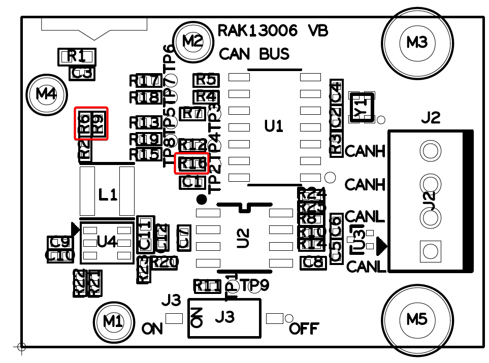
Yes, you can switch the CS signal at the connector to IO3, there are resistors to select which GPIO is used as CS. There are three options, and default is the SPI_CS signal. Alternative are IO3 or the I2C1_SCL pin.
Hello again beegee, hope you are well. I am writing again to ask you about the IO5 interrupt pin. I am programming a system that occupies this interrupt, but unfortunately I have not been able to debug the problem related to the interrupt. Looking again at your diagrams I noticed that I don’t have the resistor R4, (resistor between INT0 and VDD), is it necessary for the interrupt?, thanks!
Try to define the GPIO with internal pull-up ==> pinMode(WB_IO5, INPUT_PULLUP) before attaching the interrupt. In most cases the internal pull-ups are sufficient.