RAK11310 + Senseair S8 UART

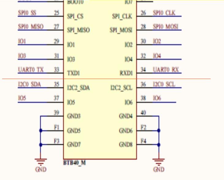
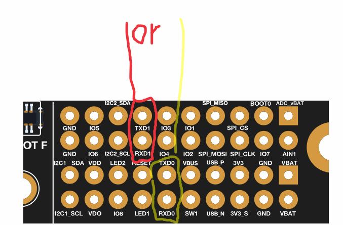
Hi all!! Can anybody help me with Senseair S8? This is CO2 sensor with UART communication. I have RAK19001 and RAK11310, sensor connected to RXD1/TXD1 pin of the board.
Below is an example code from the library. How can I adapt this code for RAK19001 + RAK11310?
Maybe you have an example that works with Senseair S8?

/*****************
Get CO2 value
*****************/

#include <Arduino.h>
#include “s8_uart.h”

/* BEGIN CONFIGURATION */
#define DEBUG_BAUDRATE 115200

#if (defined USE_SOFTWARE_SERIAL || defined ARDUINO_ARCH_RP2040)
#define S8_RX_PIN 5 // Rx pin which the S8 Tx pin is attached to (change if it is needed)
#define S8_TX_PIN 4 // Tx pin which the S8 Rx pin is attached to (change if it is needed)
#else
#define S8_UART_PORT 1 // Change UART port if it is needed
#endif
/* END CONFIGURATION */

#ifdef USE_SOFTWARE_SERIAL
SoftwareSerial S8_serial(S8_RX_PIN, S8_TX_PIN);
#else
#if defined(ARDUINO_ARCH_RP2040)
REDIRECT_STDOUT_TO(Serial) // to use printf (Serial.printf not supported)
UART S8_serial(S8_TX_PIN, S8_RX_PIN, NC, NC);
#else
HardwareSerial S8_serial(S8_UART_PORT);
#endif
#endif

S8_UART *sensor_S8;
S8_sensor sensor;

void setup() {

// Configure serial port, we need it for debug
Serial.begin(DEBUG_BAUDRATE);

// Wait port is open or timeout
int i = 0;
while (!Serial && i < 50) {
delay(10);
i++;
}

// First message, we are alive
Serial.println("");
Serial.println(“Init”);

// Initialize S8 sensor
S8_serial.begin(S8_BAUDRATE);
sensor_S8 = new S8_UART(S8_serial);

// Check if S8 is available
sensor_S8->get_firmware_version(sensor.firm_version);
int len = strlen(sensor.firm_version);
if (len == 0) {
Serial.println(“SenseAir S8 CO2 sensor not found!”);
while (1) { delay(1); };
}

// Show basic S8 sensor info
Serial.println(">>> SenseAir S8 NDIR CO2 sensor <<<");
printf(“Firmware version: %s\n”, sensor.firm_version);
sensor.sensor_id = sensor_S8->get_sensor_ID();
Serial.print(“Sensor ID: 0x”); printIntToHex(sensor.sensor_id, 4); Serial.println("");

Serial.println(“Setup done!”);
Serial.flush();
}

void loop() {

//printf(“Millis: %lu\n”, millis());

// Get CO2 measure
sensor.co2 = sensor_S8->get_co2();
printf(“CO2 value = %d ppm\n”, sensor.co2);

//Serial.printf("/%u/\n", sensor.co2); // Format to use with Serial Studio program

// Compare with PWM output
//sensor.pwm_output = sensor_S8->get_PWM_output();
//printf(“PWM output = %0.0f ppm\n”, (sensor.pwm_output / 16383.0) * 2000.0);

// Wait 5 second for next measure
delay(5000);
}

Hi,
This code looks overly complicated because they try to cover different boards, including boards with only one UART.

If you replace S8_serial with Serial1 and remove the SoftwareSerial stuff it should work.

Obviously not tested, as I don’t have the sensor, but you can try this:

/*****************
Get CO2 value
*****************/

#include <Arduino.h>
#include “s8_uart.h”

/* BEGIN CONFIGURATION */
#define DEBUG_BAUDRATE 115200

/* END CONFIGURATION */

S8_UART *sensor_S8;
S8_sensor sensor;

void setup()
{

	// Configure serial port, we need it for debug
	Serial.begin(DEBUG_BAUDRATE);

	// Wait port is open or timeout
	int i = 0;
	while (!Serial && i < 50)
	{
		delay(10);
		i++;
	}

	// First message, we are alive
	Serial.println("");
	Serial.println(“Init”);

	// Initialize S8 sensor
	S8_serial.begin(S8_BAUDRATE);
	sensor_S8 = new S8_UART(Serial1);

	// Check if S8 is available
	sensor_S8->get_firmware_version(sensor.firm_version);
	int len = strlen(sensor.firm_version);
	if (len == 0)
	{
		Serial.println(“SenseAir S8 CO2 sensor not found !”);
		while (1)
		{
			delay(1);
		};
	}

	// Show basic S8 sensor info
	Serial.println(">>> SenseAir S8 NDIR CO2 sensor <<<");
	printf(“Firmware version
		   : % s\n”, sensor.firm_version);
	sensor.sensor_id = sensor_S8->get_sensor_ID();
	Serial.print(“Sensor ID : 0x”);
	printIntToHex(sensor.sensor_id, 4);
	Serial.println("");

	Serial.println(“Setup done !”);
	Serial.flush();
}

void loop()
{

	// printf(“Millis: %lu\n”, millis());

	// Get CO2 measure
	sensor.co2 = sensor_S8->get_co2();
	printf(“CO2 value = % d ppm\n”, sensor.co2);

	// Serial.printf("/%u/\n", sensor.co2); // Format to use with Serial Studio program

	// Compare with PWM output
	// sensor.pwm_output = sensor_S8->get_PWM_output();
	// printf(“PWM output = %0.0f ppm\n”, (sensor.pwm_output / 16383.0) * 2000.0);

	// Wait 5 second for next measure
	delay(5000);
}

Hi, Bernd.
I seem to be confused with the pins. I thought that pins RXD1 and TXD1 on the RAK19001 board correspond to UART1, but judging by this picture, this is UART0. Tell me which pins to connect on the RAK19001 board to use Serial1 with RAK11310?


uart2

Different engineers designing the schematics and PCB’s for the WisBlock modules has lead to asome confusing naming.

On the RAK11310

Serial ==> USB of the RP2040
Serial1 ==> GPIO0 and GPIO1 ==> TXD1 and RXD1 on the IO Modules and pin header
Serial2 ==> GPIO4 and GPIO5 ==> TXD0 and RXD0 on the IO Modules and pin header

TXD0 and RXD0 is not used by WisBlock modules and we use it for our WisBlock Audio modules as I2S interface instead.

Serial1 ==> GPIO0 and GPIO1 ==> TXD1 and RXD1 on the IO Modules and pin header
Serial1 ==> GPIO4 and GPIO5 ==> TXD0 and RXD0 on the IO Modules and pin header

they are the same?

Typo

Serial ==> USB of the RP2040
Serial1 ==> GPIO0 and GPIO1 ==> TXD1 and RXD1 on the IO Modules and pin header
Serial2 ==> GPIO4 and GPIO5 ==> TXD0 and RXD0 on the IO Modules and pin header

thank you, that’s clear
When trying to compile your example code, it throws an error on this line:

I tried to replace “S8_serial” with “Serial1” in this line, looks like this:
"
Serial1.begin(S8_BAUDRATE);
"
Sketch compiles without errors, but then it behaves strangely.
When the sensor is connected to the board, the sketch does not upload, it gives a uploading error. When the sensor is disconnected, the sketch uploads successfully, but after connecting the sensor, nothing comes to the serial monitor.

You need to find out what S8_BAUDRATE means.

Serial1.begin() expects a baudrate like 9600 or 115200.

from lib s8_uart.h:
#define S8_BAUDRATE 9600 // Device to S8 Serial baudrate (should not be changed)

the main question, it seems to me, is why the sketch is not uploaded when sensor connected?

How is this sensor powered?
Do you have the GND of the sensor connected to the GND of WisBlock?

oops … I didn’t think about the GND, you are right. Connected the GND, now the sketch is successfully uploaded with the connected sensor. But it still does not work :slight_smile:
“SenseAir S8 CO2 sensor not found !” - serial monitor says.
If you have any ideas what else to try I would be grateful. I will look further.

I don’t know the sensor. Could it be that you have to cross RX and TX lines?

WisBlock Senseair S8
RX TX
TX RX