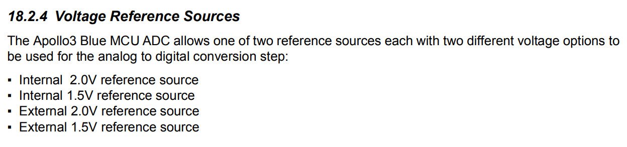
Iam currently using a RAK 11720 and i want to measure a voltage between 5-30V with ADC. I want to know if there is a way to do this with this module and how. The reason for my question is that i read some problems with the internal voltage reference why it can be difficult to measure voltages.
I saw the breakout board doesnt support ADC measurement, is this correct? I want to test the ADC of the RAK11720 but it looks like its impossible with the breakout board. Can someone help me out with this problem?
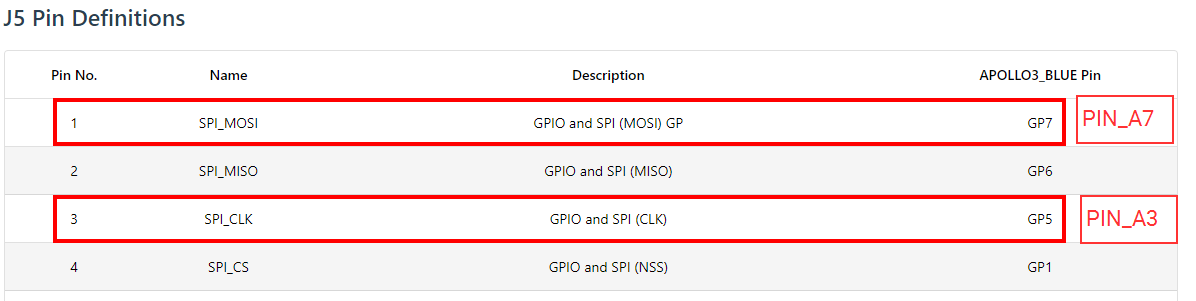
I tried to use these pins but i dont receive any raw data. This is my code, Iam using a 120K and 15 K resistor for voltage dividing and i measure a voltage of 0.5V on pin 7. Can you help me with this?
/***
* This example read WB_A1 pin in analog signal.
***/
//Set pin number
//#if defined(WISBLOCK_BASE_5005) || defined(WISBLOCK_BASE_5005_O)
//uint8_t analogPin = WB_A1;
//#else
#warning Please set the right pin refer to the documentation
uint8_t analogPin = WB_SPI_MOSI; //analog Pins
//uint8_t analogPin = PIN_A7; //analog Pins
//#endif
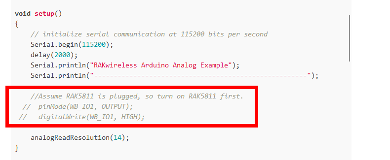
void setup()
{
// initialize serial communication at 115200 bits per second
Serial.begin(115200);
delay(2000);
Serial.println("RAKwireless Arduino Analog Example");
Serial.println("------------------------------------------------------");
//Assume RAK5811 is plugged, so turn on RAK5811 first.
// pinMode(WB_IO1, OUTPUT);
// digitalWrite(WB_IO1, HIGH);
analogReadResolution(14);
}
void loop()
{
float max, ref;
switch (udrv_adc_get_resolution()) {
case UDRV_ADC_RESOLUTION_6BIT:
{
max = 64.0;
break;
}
case UDRV_ADC_RESOLUTION_8BIT:
{
max = 256.0;
break;
}
case UDRV_ADC_RESOLUTION_10BIT:
default:
{
max = 1024.0;
break;
}
case UDRV_ADC_RESOLUTION_12BIT:
{
max = 4096.0;
break;
}
case UDRV_ADC_RESOLUTION_14BIT:
{
max = 16384.0;
break;
}
}
switch (udrv_adc_get_mode()) {
case UDRV_ADC_MODE_DEFAULT:
default:
{
#ifdef rak11720
ref = 2.0;
#else
ref = 3.6;
#endif
break;
}
#ifdef rak11720
case UDRV_ADC_MODE_1_5:
{
ref = 1.5;
break;
}
#else
case UDRV_ADC_MODE_3_3:
{
ref = 3.3;
break;
}
case UDRV_ADC_MODE_3_0:
{
ref = 3.0;
break;
}
case UDRV_ADC_MODE_2_4:
{
ref = 2.4;
break;
}
case UDRV_ADC_MODE_1_8:
{
ref = 1.8;
break;
}
case UDRV_ADC_MODE_1_2:
{
ref = 1.2;
break;
}
#endif
}
int adc_value = analogRead(analogPin);
Serial.printf("ADC pin value = %d\r\n", adc_value); // print analogPin adc value
// This is the formula to get the input voltage of RAK5811:
Serial.printf("Voltage value = %f V\r\n", ref*(((float)adc_value)/max)*(5.0f)/(3.0f));
delay(1000);
}
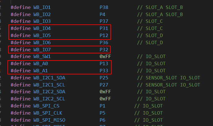
with the PIN_A7 and PIN_A3 its i couldnt measure ADC. But i soldered a cable to pin 32 of the module and this one is working. So this problem is solved.
Is there a way to use a external reference of 3.3V. I need this 3.3V external reference instead of the 1.5 or 2V internal reference.