RAK11720 Analog signals

Hello,

I’ve doing some tests with RAK11720 on my custom board, and I have a couple of questions regarding RAK11720 compatibility with:

  • VBat measurement:
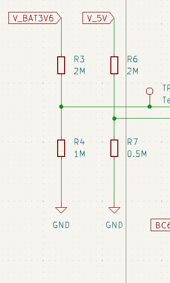
    • Currently I’ve used the same resistor divider 1M/1.5M that RAK boards uses, but it’s not clear to me which port to use currently I have it on ADC3/PIN26/IO4 (probably incorrect). Also I see on another topic that probably I need to adapt the resistor divider.
  • Analog Input RAK5801
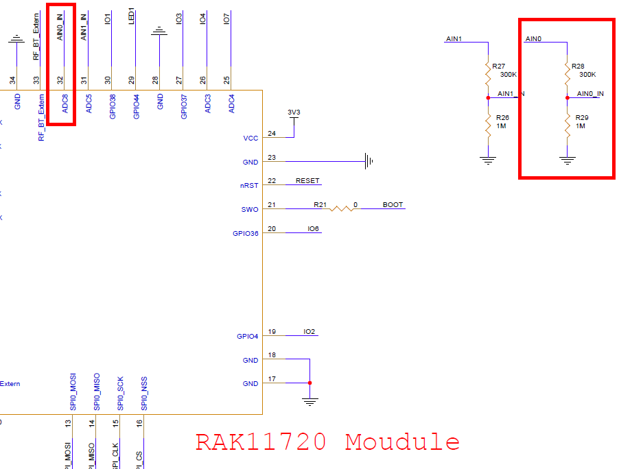
    • Is this module compatible with RAK11720? Appears to use ADC5/PIN31/AIN1_IN and ADC6/PIN32/AIN2_IN Correct?. Maybe here is neccessary to adapt the opamp resistors too?

Thanks in advance

RUI3 api.system.bat.get() is designed to work with the WisBlock Base Boards.

RUI3 uses for the battery voltage reading the ADC8 pin.

As you can see in the schematic, due to range limitations of the internal ADC, there is a second resistor divider with 300k/1M in addition to the 1M/1.5M.

RAK5801 will use AIN1, which is connected to ADC5 and WB_IO4, which is connected to ADC3.

Hello @beegee

I have now more or less clear, many thanks.

I see that with RAK11720 I can use three ADC’s at the same time? For example:

  • Battery Voltage on ADC8 Pin32
  • AIN0 from RAK5801 on ADC5 Pin31
  • AIN1 from RAK5801 on ADC4 Pin26

Should work, but I never tried it.

Hello @beegee

I’ve decided to discard RAK5801 and use an external I2C device to handle 0-20mA inputs.

Now I’m using ADC8 to read battery voltage (0 to ~4.4 Vin) and ADC5 to read a solar panel voltage (0v to ~7.5V).

I see some imprecission on voltage readings and I think that my resistor dividers are maybe very large. Can you point me the recommended resistor values without sacrifice a lot of power consumption?

I cannot find any impedance limitations in the data sheet of the Apollo3, but I found this:

Hello again!

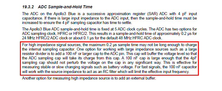
Many thanks for your time, I’ve soldered 100nF capacitor to both inputs and now the values appears spot on :wink:

I have another question related to analog reading…
My application is fully event driven so the only thing I have on loop() is the typical api.system.sleep.all();

I’ve done the analog tests with this line commented (so no sleep) but as soon as I enabled it, the analog readings are of very low value.

Tried to do a for loop to get 10 sampling values, and also discarding another 10 values before entering this loop. Appears to improve, but still very low.

I’m suspecting that with sleep enabled the MCU appears to turn off the ADC and maybe doesn’t have enough time to charge the caps?

Do you see a difference in the power consumption with api.system.sleep.all() active or not?

The loop is called by a scheduler of RUI3, if it is empty, RUI3 should go into sleep by itself if it is empty and if you enabled automatic sleep before with api.system.lpm.set(1)

Hello Bernd

If I comment //API.system.sleep.all() then, the analog readings are correct (loop empty).

The problem comes enabling this line. The application is a low power one.

Let me ask differently:

How much current do you measure on the supply line with api.system.sleep.all()

How much current do you measure on the supply line without api.system.sleep.all() and api.system.lpm.set(1) in the setup() function.

I expect no difference if you enable the low power mode with api.system.lpm.set(1)

Hello Bernd, today I’m testing your suggestions and show you the results as detailed as possible:

  • With loop() empty and api.system.lpm.set(1):

    • Analog values reading: GOOD

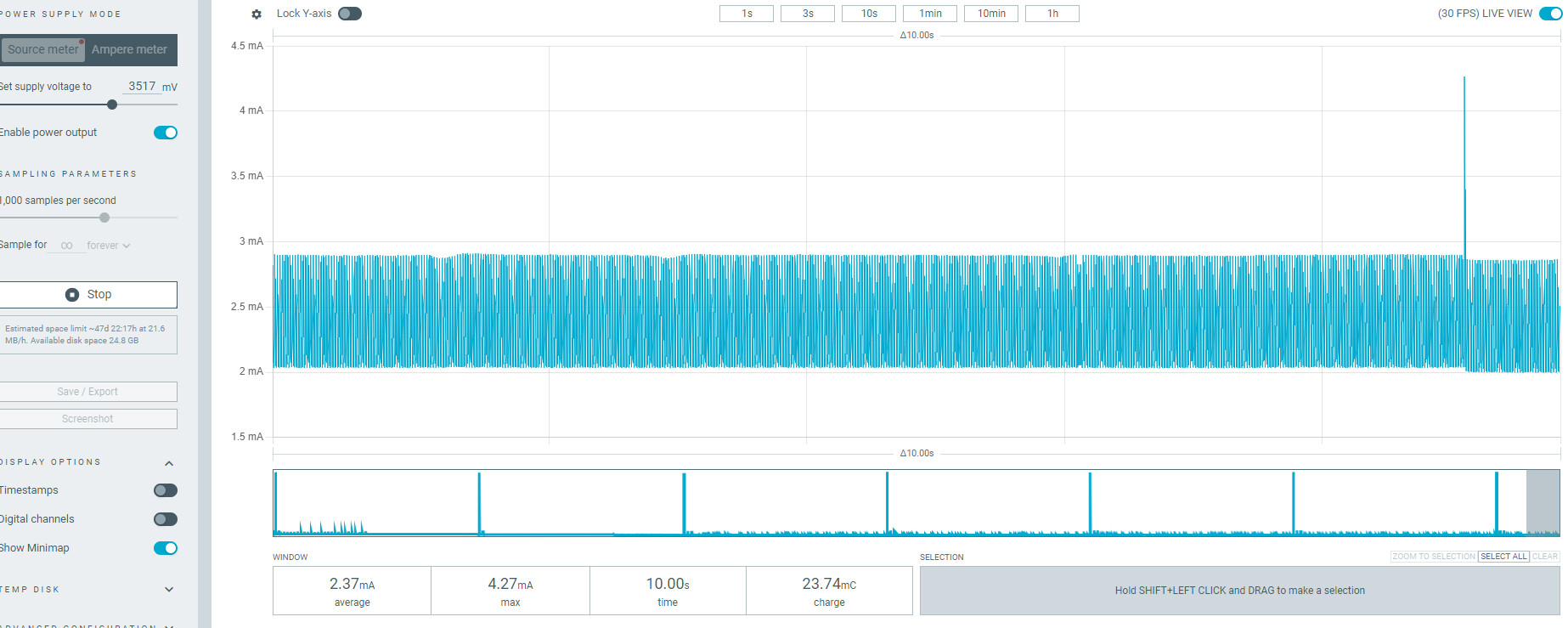
    • PPKII power consumption: 2.38mA

    • I’ve tried to send AT+LPM=0 and AT+LPM=1 and no changes are observed regarding power consumption.

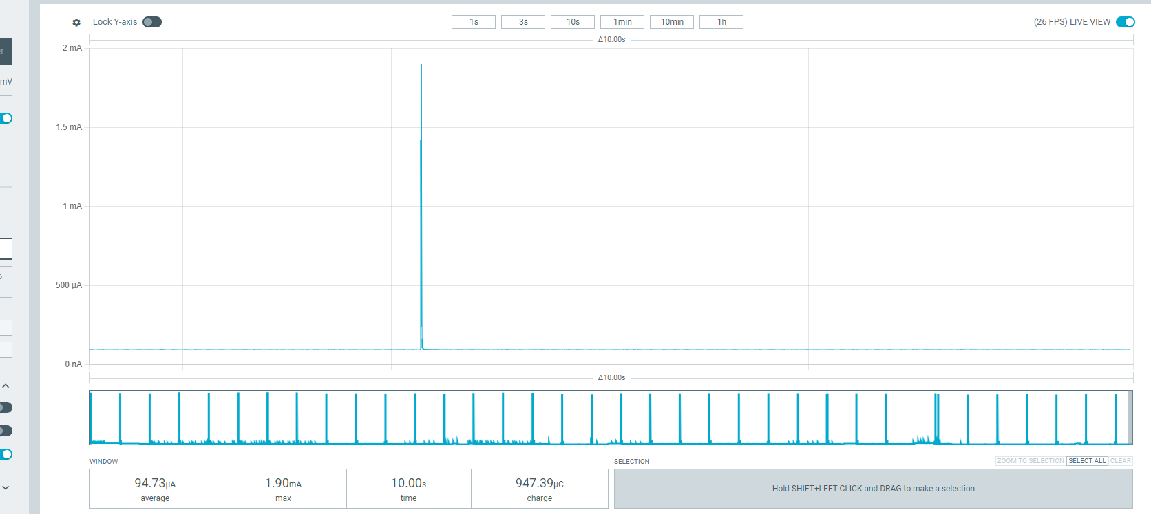
    • As soon as I put AT+SLEEP=120000 the MCU goes to sleep and power consumption drops to ~96uA on my board, but the next analogRead gets wrong values (near 0volts).

  • loop() with api.system.sleep.all();

    • Analog values reading: BAD (values near 0volts)
    • PPKII power consumption: ~96uA
    • Sending AT+LPM=0 or AT+LPM=1 has no change

To give you more info, the program is asyncronous (no loop). I have a task called main_timer_handler that gets called every minute:

api.system.timer.create(RAK_TIMER_0, main_timer_handler, RAK_TIMER_PERIODIC);
if (g_system_tick_timer != 0)
{
	// Start a timer.
	api.system.timer.start(RAK_TIMER_0, g_settings.heartbeat_interval * 60000, NULL);
	MYLOG("TMR", "Main timer started");
}

Inside that task I’m calling a function to read analog values from battery and solar panel input like this (samples is unused here at the moment):

float read_ain(uint8_t input, uint8_t samples=5){
	prevent_sleep = true;
	//Discard first value
	if (input == 1){
        //Discard first three values
		analogRead(MCU_A0);
		analogRead(MCU_A0);
		analogRead(MCU_A0);
        return (analogRead(MCU_A0) * batt_adc_ratio);
        }
    else if(input == 2){
        //Discard first three values
		analogRead(MCU_A1);
		analogRead(MCU_A1);
		analogRead(MCU_A1);
        return (analogRead(MCU_A1) * solar_adc_ratio);
        }
}

The boolean prevent_sleep is a test that I’ve done in conjuntion with

void loop()
{
	if (!prevent_sleep)
	    api.system.sleep.all();
}

In order to avoid calling sleep while adc reading happens, but appears to have no effect.

Also, I’ve observed that if I put AT+BAT=? while sleeping the reading is also wrong

Regards!