I’d like to remove some of the zero ohm links on the RAK12500. Specifically I’d like to remove the R56 and R58 links, to isolate the UART from the rest of the WisBase, and I’d like to remove R90, which ties the NRESET signal to “IO6” which in Slot A corresponds to the IO line that also controls 3V3_S. (I’m using Slot A to be able to get the PPS to one of the header pins on the Baseboard)
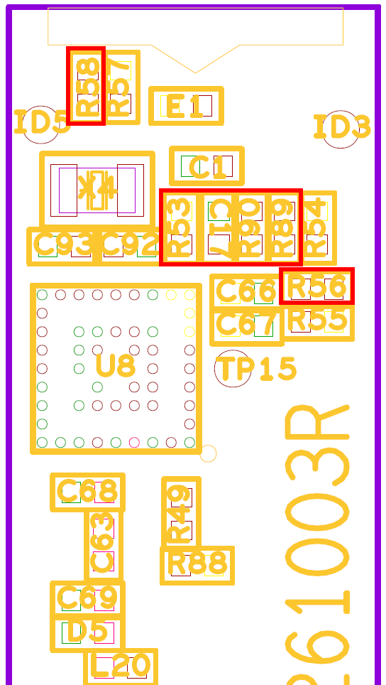
The short question is probably to @beegee: Do you have an image from the design files that shows where these resistors (56, 58, 90) are located.
The contextual longer question is about powering down the ZOE-M8 chip. Careful reading of the datasheet, hardware integration manual and protocol description hasn’t helped all that much. I think that with 3V3 connected to the Vbackup, “hardware backup” mode is nothing more than switching the 3V3_S off. Then is seems I can just reapply 3V3_s and the ZOE-M8 wakes up in “hot start”. If NRESET is tied to the 3V3_S control signal, along with load capacitor C17, I think that reset will be asserted as the power comes on. Since NRESET also resets the RTC based time estimate, this means the ZOE-M8 will wake up in a “cold start”. That’s why I think I need to remove R90.
The second question is more generally has anyone been here before? Is there anything I should do that has a bit more finesse than just yanking the 3V3_S power rail. Disabling the PPS and checking that AssistNowAutonomous isn’t busy seem like good ideas.
I’ll explore this over the next few days and report what I find, but if someone has already trodden this path I’d like to hear what you learned.